Thanks for that! It's seeing competed projects like that that keep me on this forum, really interesting to see stuff like that. Love it! Now will you please post another video of it working?
The wiring isn't obviously that much of a mess. Based on what I've seen and what you've said I am out of ideas beyond what I've already commented. If you are still looking for ideas then I would like to see a neat drawing that shows not only the circuit but exactly which wires are used in which cable for what purpose, that might give some ideas.
Thanks again for showing that, impressive project.
This is it doing what I call auto slab. Once I get to a square cant. This was several iterations ago, prior to the added servo that controls the throttle of the engine. The throttle control will bring the engine down to an idle after a cut and prior to returning. I really liked that new feature!
All of the kinks have not been completely been ironed out, but it worked well yesterday and today. This saw mill started as a golf cart engine with cart tires and a basic hand winch to lift the head and push manually down the track. I have had tremendous help from this forum from a number of people, but @cattledog and @wildbill have walked me through this project step by step (often times painful baby steps for me). I had no clue what a code was prior to this project. So, they deserve most of the credit. It has been very interesting to learn though.
You will also notice the rats nest of wires that is inside the box....
However, unless you want the pain of learning a whole new software package a pencil and paper are fine. Just take your time, use a ruler and make it neat.
Actually, I have a cnc router and I just recently bought some bits and blank pcb boards. I have not done anything with them. I bought the bits and pcb with the intentions to eventually create a easier to connect to pcb for this mill. However, I have a feeling that is going to be quite the learning curve in itself….
I am really not sure if I went that route if I should use the actual mega board or the 2560 chip? I have know idea how to do any of this, but I feel like if I could create a main board with screw lugs for all of my connections, I would be much better off.
The Mega does not really work with a PCB as it doesn't have the pins needed to connect to one. How many pins do you need? There are plenty boards the can easily be pointed on a PCB, some by being directly soldered, some by being plugged into headers.
Im not sure that I understand. I think as of right now I am using 12 digital pins and 4 analog.
What I was planning to do is cnc a pcb board that had female headers. These female headers would be where the male headers of the mega would plug in to. I would then have traces on the pcb to screw lugs that I could connect my wires to the correct pin of the mega. I am using several tip120’s to allow the output of the mega to switch relays. I was hoping to at least include them also to the pcb, so I wouldn’t have multiple boards to connect to. This would allow me to have it all on one “main” board.
I am also using the two separate motor driver boards. I have wondered if I could add the mosfets, relays and whatever else is needed to control my motors via pwm as well. This would truly make it a main board, but I am not sure this is feasible.
However, I have no clue what the best/easiest way to do this is. I am open to any suggestions.
In the meantime, the sawmill has worked great with the latest code. Noise issues Haven’t seemed an issue
@PerryBebbington
Here is a schematic I drew up with fusion360. It apparently has eagle built in to it now. I am fairly good with fusion, but this was quite difficult. I never knew that eagle was a part of fusion, I am going to continue to play around with it in hopes of making a circuit board at some point. I have the file saved for eagle, but it will not let me post it here.
Unfortunately I am very confused by that, here is 1 example but there are others.
In the second image you have hand drawn in various colours. One of the hand drawn bits says 'Cat 6E cable twisted pair goes through drag chain to servo motor'. According to the schematic there are 2 wires used in this cable to the servo motor, however, there are clearly other wires that go to the servo motor but there is no indication of how they get there.
A lot of what is on the schematic is unreadable.
To stand a chance of helping the schematic needs to be clear, readable and complete.
I am particularly interested in seeing how the cables that join each part up are configured, with a representation that shows completely what joins to what and how.
Yes, that pair of wires is CAT6 and it does run through the drag chain. That is the only pair of wires that I am using in the CAT6 cable. The other pairs are available to be used if needed.
There is a 5v+ and 5v - going from the 12-5v converter to the servo motor. These wires do not go through the drag chain. The converter is very close to the servo motor 12 inches or so.
Do you mean how they are physically attached (screw terminal, solder, header pins, etc?
It is hard to get a jpeg picture with everything in it, and it be large enough to read. I will try to get a better picture.
That does not make sense. How can some of the wires to the servo motor go through the drag chain but not others? Either the motor is fed via the drag chain or it is not. If it is then all the wires to it must go through the drag chain, if it is not then none of the wires go through the drag chain.
What I see, is a disregard for schematic conventions. So, it's a diagram and it's neatly drawn, but extremely ambiguous.
To make it clearer, there is supposed to be a one to one correspondence between every important component, connection, and conductor in the diagram, and the same things in the device.
The power source for the servo is coming from the 5-12v converter. The converter is connected to a 12v battery and located just a few inches from the actual servo. However, the arduino is inside of the enclosure (both the enclosure with buttons and arduino inside, and the converter can be seen in the first video I posted) that has the buttons mounted to it. The “signal” wire that goes to the servo goes from the arduino through the drag chain to the servo motor. The signal wire is in a CAT6 cable. Because I have read that grounding one of the pairs of a twisted pair will help reduce noise, the mate of the signal wire (wire that is twisted with the signal wire) also goes through the drag chain to ground at the arduino.
Again, I know the wiring is shotty. And apparently the schematic as well.
This may be true, but it is not intentional. I don’t know how to draw a schematic. But, I am willing to learn. I was hoping if pencil and paper was fine, this would work, I was wrong obviously.
Ah! I did not realise that, thank you. So the power to the servo does not pass along a long cable because it is located close to the servo. That's fine.
That's good but something about what you said worries me. You are correct to say that grounding one of the wires helps reduce noise but miss that if you don't ground it there is no complete circuit for the signal. Is this something you didn't understand or do you understand it and missed it from the description? Something fundamental to keeping noise out is keeping the net flow of current in a cable zero. This means doing exactly what you describe, the signal and its associated return are in 2 wires twisted together. As the current for the signal flows to the servo and back along the other wire in the twisted pair the net current in those 2 is zero. Aim to do that in all situations and you won't go far wrong.
However, looking at your first image in reply #30 there is a 12V battery and convertor powering the servo in the bottom right of the image. That battery also powers the head lift motor and the head motor driver. If I understood correctly these are all located together away from the Arduino. However, that schematic shows various other wires from the Arduino to those devices along with a ground wire between them. I am not at all clear how that all links, which cable carries what signals and where the ground return is for those signals.
I don’t know how to draw a schematic. But, I am willing to learn. I was hoping if pencil and paper was fine, this would work, I was wrong obviously.
You were not wrong! Some of the best schematics on here are done with paper and pencil. What matters is it is clear. Some parts of the schematic in reply are unreadable. Parts that cannot be read are useless, whether created on a computer or with a pencil and paper.
It would help to draw a schematic for each physically separate unit and clearly show the cable in and out of each unit that links them together. This could be and probably should be separate sheets.
Finally, is this discussion helping you? You said it all works, which is good, so is this just a matter of making it more 'professional' and learning something, or do you still need to actually fix a problem?
Yes, I am learning. It is working fine. So, I will probably not be making any changes until necessary, or I add something to the mill. However, I would like to know the correct way to do it for the future. Ultimately, I would like to create a pcb that would simplify my connections inside the box.
To make my connections to the mega. I know this isn’t ideal, but I don’t know a good way of doing it….
I did make a simple pcb on my cnc yesterday…. Pretty neat…. It was just a test run, but I used fusion to create the schematic. It was a fairly simple design, but I think it is a possibility now. Would it be realistic to create a pcb that I could use with mill and had the components needed to serve as a motor driver for the winch and scooter motor? Or is this way above my capabilities?
As for the wiring of the servo, i have the the twisted pair that is twisted with the signal wiring rubbing to a ground pin on the arduino. It then runs through the drag chain twisted with the signal wire to the 12-5v converter. It is there connected to 5v- on the converter and the signal wire goes to the servo. I may have left the twisted ground to the 5v- off of the schematic. I can’t remember. Does that help any?
Don't use a Mega for that kind of thing, the way you connect is, err, inconvenient. If you use, for example, a Nano Every you can mount it on a PCB either with header pins into a socket or directly soldered to the PCB. Lots of other boards that can be mounted on a PCB easily.
I've never heard of anyone making a PCB on a CNC machine, please show a photo of it, I am intrigued. The usual way is to design it using something like KiCAD or Eagle then use a PCB manufacturer to make it. I use https://jlcpcb.com in China. I think you are in the US, you have https://oshpark.com/. Both make small quantities for a modest price.
Look at this this way, I could not build that machine, but my nephew could. If he built something like that he's ask me to do the electronics, which I'd find easy. You've done both! I am sure you are more than capable of making a PCB with a bit of help on here.
As for the wiring of the servo, i have the the twisted pair that is twisted with the signal wiring rubbing to a ground pin on the arduino. It then runs through the drag chain twisted with the signal wire to the 12-5v converter. It is there connected to 5v- on the converter and the signal wire goes to the servo.
The ground wire is part of the signal circuit to the servo, so the ground wire in the twisted pair should go to the servo, not the converter. It probably doesn't make much difference, but by connecting it to the converter you are making the signal 0V pass through the same wire that carries the current to the servo. The wire will have resistance, current through resistance means voltage. Spiky current means spiky voltage. By doing what you have done you are adding voltage spikes to the servo signal. Each time you do something like that you add a bit more noise to the whole system.
I will check in to this. I really understand why one can be mounted and one can't.
Not quite sure I understand. There are three wires that go to the servo. one is 5v positive connected to the the 5v output of converter. one is signal which is one of the wires in the twisted pairs that goes back to the aruduino. The other is ground. I have this wire AND the other wire of the twisted pair connected together at the 5v ground terminal of the converter.
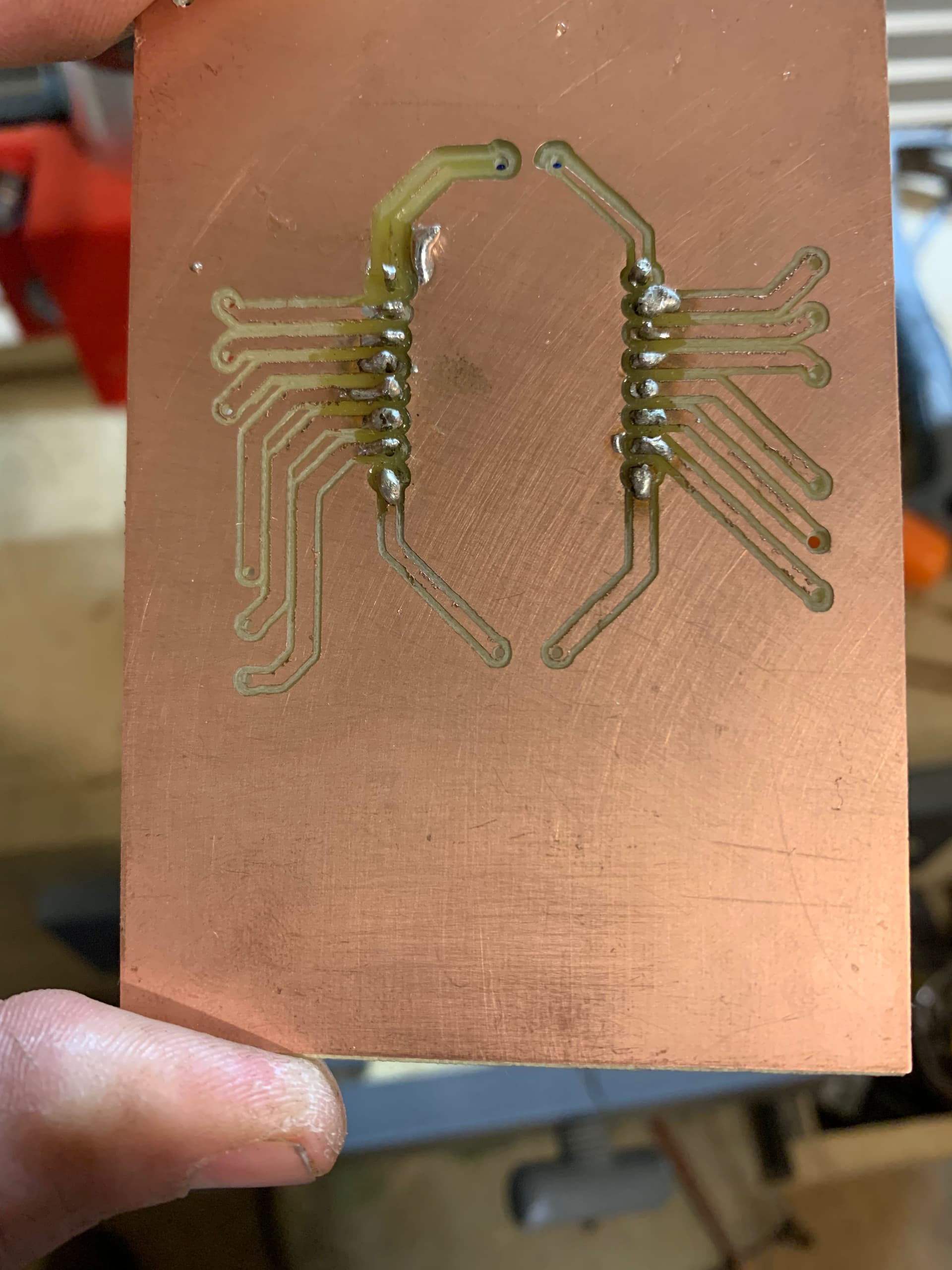
Here is a quick video and few pictures of he pcb I routed. This was my first time trying this. As you can see in the first two traces, my bit was too big and I routed out all of the copper (no good). However, after making a few adjustments, I think it would be useable.
I designed in fusion which has eagle now built in to it. I am a long ways from understanding it, but it did atleast come out useable. I didn't really have any big intentions with this board. I figured I would mess it up, but it was supposed to be for a wemos mini to mount to and the traces run to screw terminals. This just gives me a simple way to connect. Don't look too closely at the soldering job.... Yea, I'm not very good at that either.....