Hi everyone,
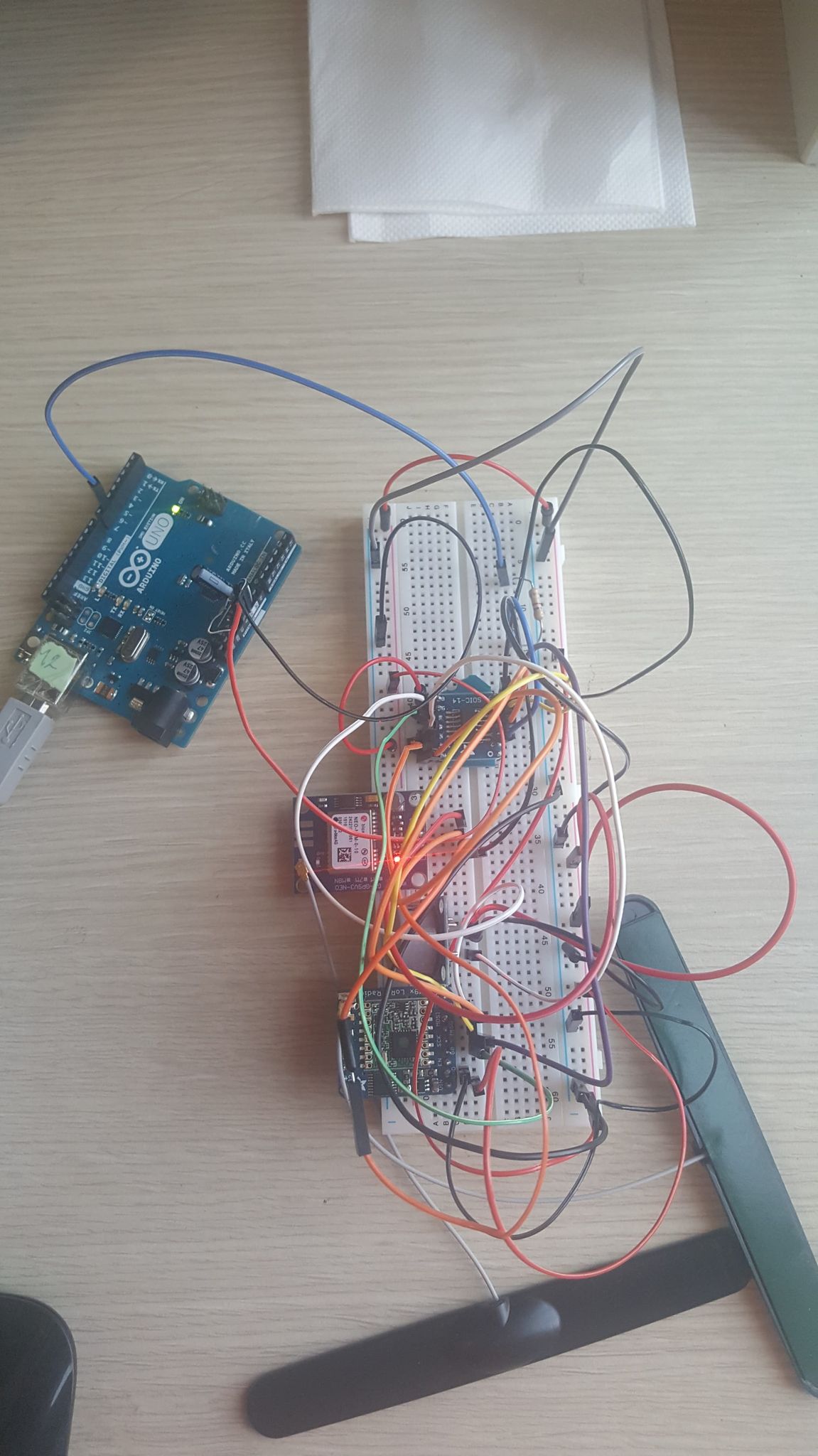
I'm building a device that should detect PM10 concentration values in the air with a simple sensor and send them together with its latitude and longitude to a server using a LoRa module.
I'm using an attiny1604 (I'm kinda forced to use it) as a microcontroller, the adafruit ultimate breakout as GPS module and a RFM9X for the transmission.
The problem is the GPS as I can send and read the PM10 values from the server, while I can only get 0.00 for latitude and longitude. I made tests close to windows and outdoor and I still get 0.00.
I'm using jtag2upidi (megaTinyCore) as programmer and default timer.
For the library I'm using TinyGPS++.
I used "prova" in order to see if the code inside the while cycles works and it doesn't as prova will always be==1.
Here the main code (sorry some comments are in italian)
#include <TinyGPS++.h>
#include <SoftwareSerial.h>
#define gpsPort ssGPS

#include <Arduino.h>

#include "LoRaWAN.h"
#include "secconfig.h"

/******************************
 DEFINIZIONI MODULO LoRa
 ******************************/
#define DIO0 1 //PIN FISICO 3
#define NSS 0 //PIN FISICO 2
RFM95 rfm(DIO0, NSS);
// Definisce la lunghezza del buffer dati
uint8_t Data_Length = 0x10;
// Definisce il layer LoRaWAN
LoRaWAN LoRa = LoRaWAN(rfm);
// Frame Counter per contare ogni Payload inviato
unsigned int Frame_Counter_Tx = 0;

/******************************
 DEFINIZIONI MODULO GPS
 ******************************/
static const int Rx = 7, Tx = 6;
static const uint32_t GPSBaud = 9600;

// The serial connection to the GPS device
SoftwareSerial ssGPS(Rx, Tx);
float lati, longi;
int latid, longid;
float latif, longif;
// The TinyGPS++ object
TinyGPSPlus tinyGPS;
// sensore
#define sensor 3

int prova=1;

void setup( ) {
  Serial.begin(9600);
//Inizializzo il modulo RFM
 rfm.init();
/*Inizializza le chiavi di sessione ed applicazione e l'indirizzo del
nodo per il joining tra Nodo e Network Server attraverso tecnica ABP*/
 LoRa.setKeys(NwkSkey, AppSkey, DevAddr);
 pinMode(sensor,INPUT);

//   pinMode(Rx,INPUT);
//   pinMode(Tx,OUTPUT);
  ssGPS.begin(GPSBaud);
}
void loop( ) {

 delay(4000);
 //smartDelay(1000);
 while (ssGPS.available()){
      tinyGPS.encode(ssGPS.read());
      prova=3;
 }
 unsigned char Data[Data_Length];
 int val=analogRead(sensor);
 while(tinyGPS.location.isValid()){
 lati=tinyGPS.location.lat();
   //longi=tinyGPS.location.lng();
   prova++;
 }

//aumento il Frame Counter
 Frame_Counter_Tx++;

 //Provo a stampare e trasmettere distanza come parte intera e decimale --> sprintf per l'attiny ha funzionalità limitate
  char *sgn = (lati < 0) ? "-" : "";
  //lati = (lati < 0) ? -lati : lati;
  latid = lati;
  latif = lati - latid;
  int latiff = trunc(latif * 100);


//Creo la stringa in cui stampo il buffer Data contenente la stringa di invio
 Data_Length = sprintf(Data,"Valore ~  %d ppm, Latitudine :%s%d.%02d , prova %d", val,sgn, latid, latiff, prova ); // 33 BYTE
/*Send_Data già modificato nella libreria; mancavano alcuni parametri che
permettevano la trasmissione a certi SF(Spreading Factor) e BW(Larghezze
di Banda)*/
//A fine sketch sono riportati i canali con SF e BW modificati nella libreria (sono riportati come riferimento per ricordarsene)
//txParameter viene scelto uguale a 5 perchè individua la casistica 5 per
//la trasmissione; quindi trasmetto ad un SF7 con BW di 125 kHz
 int txParameter=5;
/*Controllo sulla quantità di pacchetti inviati; considerando i tempi necessari
a sistemare e recuperare il sistema sotto terra, non volevamo inviare pacchetti fino a che le batterie non si fossero drenate;
si è quindi inserito un controllo sul contatore, in modo che quando esso arriva a
2000 la trasmissione si conclude definitivamente.*/
if (Frame_Counter_Tx < 2000)
 {
 LoRa.Send_Data(Data, Data_Length, Frame_Counter_Tx,txParameter);
 }
}
here secconfig.h
unsigned char NwkSkey[16] = { 0x01, 0x02, 0x03, 0x04, 0x05, 0x06, 0x07, 0x08,
 0x09, 0x10, 0x11, 0x12, 0x13, 0x014, 0x15, 0x16 };
unsigned char AppSkey[16] = { 0x01, 0x02, 0x03, 0x04, 0x05, 0x06, 0x07, 0x08,
 0x09, 0x10, 0x11, 0x12, 0x13, 0x014, 0x15, 0x16 };
unsigned char DevAddr[4] = { 0x00, 0x00, 0x00, 0x02 };
I'll also post what I get on the server.