problem writing to DS1307

Im just using the standard code that comes on the Arduino software just to set the time. Iv done this before with another arduino board and DS1307 chip and it worked fine.

//Arduino 1.0+ Only
//Arduino 1.0+ Only

#include "Wire.h"
#define DS1307_ADDRESS 0x68
byte zero = 0x00; //workaround for issue #527

void setup(){
  Wire.begin();
  Serial.begin(9600);
  setDateTime(); //MUST CONFIGURE IN FUNCTION
}

void loop(){
  printDate();
  delay(1000);
}

void setDateTime(){

  byte second =      00; //0-59
  byte minute =      19; //0-59
  byte hour =        21; //0-23
  byte weekDay =     4; //1-7
  byte monthDay =    27; //1-31
  byte month =       10; //1-12
  byte year  =       12; //0-99

  Wire.beginTransmission(DS1307_ADDRESS);
  Wire.write(zero); //stop Oscillator

  Wire.write(decToBcd(second));
  Wire.write(decToBcd(minute));
  Wire.write(decToBcd(hour));
  Wire.write(decToBcd(weekDay));
  Wire.write(decToBcd(monthDay));
  Wire.write(decToBcd(month));
  Wire.write(decToBcd(year));

  Wire.write(zero); //start 

  Wire.endTransmission();

}

byte decToBcd(byte val){
// Convert normal decimal numbers to binary coded decimal
  return ( (val/10*16) + (val%10) );
}

byte bcdToDec(byte val)  {
// Convert binary coded decimal to normal decimal numbers
  return ( (val/16*10) + (val%16) );
}

void printDate(){

  // Reset the register pointer
  Wire.beginTransmission(DS1307_ADDRESS);
  Wire.write(zero);
  Wire.endTransmission();

  Wire.requestFrom(DS1307_ADDRESS, 7);

  int second = bcdToDec(Wire.read());
  int minute = bcdToDec(Wire.read());
  int hour = bcdToDec(Wire.read() & 0b111111); //24 hour time
  int weekDay = bcdToDec(Wire.read()); //0-6 -> sunday - Saturday
  int monthDay = bcdToDec(Wire.read());
  int month = bcdToDec(Wire.read());
  int year = bcdToDec(Wire.read());

  //print the date EG   3/1/11 23:59:59
  Serial.print(month);
  Serial.print("/");
  Serial.print(monthDay);
  Serial.print("/");
  Serial.print(year);
  Serial.print(" ");
  Serial.print(hour);
  Serial.print(":");
  Serial.print(minute);
  Serial.print(":");
  Serial.println(second);

}

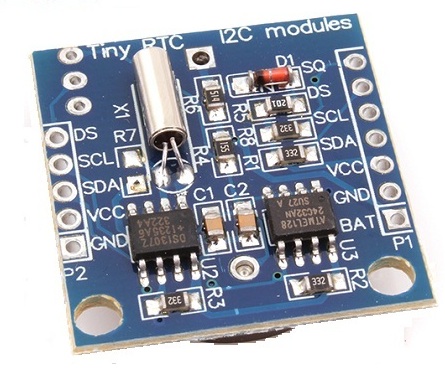
Thats the code that i am using to load the information into the DS1307. Iv got SDA connected to A4 and SCL connected to A5 and then 5v and gnd connected to VCC and GND.

when i run this code and i run the Serial Monitor it comes back with 165/165/165 45:165:165.

Iv tried using another piece of code

#include <Wire.h>
#include <Time.h>
#include <DS1307RTC.h>

const char *monthName[12] = {
  "Jan", "Feb", "Mar", "Apr", "May", "Jun",
  "Jul", "Aug", "Sep", "Oct", "Nov", "Dec"
};

tmElements_t tm;

void setup() {
  bool parse=false;
  bool config=false;

  // get the date and time the compiler was run
  if (getDate(__DATE__) && getTime(__TIME__)) {
    parse = true;
    // and configure the RTC with this info
    if (RTC.write(tm)) {
      config = true;
    }
  }

  Serial.begin(9600);
  while (!Serial) ; // wait for Arduino Serial Monitor
  delay(200);
  if (parse && config) {
    Serial.print("DS1307 configured Time=");
    Serial.print(__TIME__);
    Serial.print(", Date=");
    Serial.println(__DATE__);
  } else if (parse) {
    Serial.println("DS1307 Communication Error :-{");
    Serial.println("Please check your circuitry");
  } else {
    Serial.print("Could not parse info from the compiler, Time=\"");
    Serial.print(__TIME__);
    Serial.print("\", Date=\"");
    Serial.print(__DATE__);
    Serial.println("\"");
  }
}

void loop() {
}

bool getTime(const char *str)
{
  int Hour, Min, Sec;

  if (sscanf(str, "%d:%d:%d", &Hour, &Min, &Sec) != 3) return false;
  tm.Hour = Hour;
  tm.Minute = Min;
  tm.Second = Sec;
  return true;
}

bool getDate(const char *str)
{
  char Month[12];
  int Day, Year;
  uint8_t monthIndex;

  if (sscanf(str, "%s %d %d", Month, &Day, &Year) != 3) return false;
  for (monthIndex = 0; monthIndex < 12; monthIndex++) {
    if (strcmp(Month, monthName[monthIndex]) == 0) break;
  }
  if (monthIndex >= 12) return false;
  tm.Day = Day;
  tm.Month = monthIndex + 1;
  tm.Year = CalendarYrToTm(Year);
  return true;
}

and when i run this it comes back with DS1307 Communication Error :-{ Please check your circuitry. Which is obviously what its supposed to do when it encounters a problem hence the reason for explaining my pin configuration.

Is it possible iv got a duff board or is it more likely to be me :). Iv ordered another DS1307 just incase.

Thanks in advanced.

The first thing to do is run an i2c scanner program and detemine if the ds1307 is recognized on the bus

// I2C Scanner
// Written by Nick Gammon
// Date: 20th April 2011

#include <Wire.h>

void setup() {
  Serial.begin (115200);

  // Leonardo: wait for serial port to connect
  while (!Serial) 
    {
    }

  Serial.println ();
  Serial.println ("I2C scanner. Scanning ...");
  byte count = 0;
  
  Wire.begin();
  for (byte i = 8; i < 120; i++)
  {
    Wire.beginTransmission (i);
    if (Wire.endTransmission () == 0)
      {
      Serial.print ("Found address: ");
      Serial.print (i, DEC);
      Serial.print (" (0x");
      Serial.print (i, HEX);
      Serial.println (")");
      count++;
      delay (1);  // maybe unneeded?
      } // end of good response
  } // end of for loop
  Serial.println ("Done.");
  Serial.print ("Found ");
  Serial.print (count, DEC);
  Serial.println (" device(s).");
}  // end of setup

void loop() {}

so after running this little program and then running the Serial monitor it came up with the following:

"I2C scanner. Scanni address: 80 (0x50)
Done.
Found 1 device(s).
ÒZÿà§l"

iv tried changing the address to 0x50 to see if thats the problem but im just getting nothing back from the little DS1307. Iv no idea what the problem is at the minute or how i can get it to read/write to it.

craig20102010:
iv tried changing the address to 0x50 to see if thats the problem but im just getting nothing back from the little DS1307. Iv no idea what the problem is at the minute or how i can get it to read/write to it.

Which DS1307 hardware are you actually using?
Circuit schematics?
Did you make a DS1307 module of your own?

You are telling nothing about the DS1307 circuit schematics, so I make a guess:
Are you possibly using one of those shitty modules labeled "Tiny RTC"?

Picture:

Or what?

Those shitty "Tiny RTC" modules have TWO I2C devices on board:
1.) DS1307
2.) EEPROM 24C32

When running an I2C scanner sketch with that "Tiny RTC" module, you'll find the EEPROM 24C32 at address 0x50. An EEPROM is NOT an RTC!

As jurs says, the i2c scanner has found the eeprom on the bus, but not the ds1307. It should be at address 0x68. You have a defective module or chip.
Take a look at the pin diagram on this data sheet and use a multimeter to check, with the module disconnected, if you can find continuity between the power, ground, sda, and scl input pins to the chip leads. Also check for shorts between any two lines or from a line to ground. If everything is properly connected then there is an internal defect in the chip. http://datasheets.maximintegrated.com/en/ds/DS1307.pdf

jurs:
Which DS1307 hardware are you actually using?
Circuit schematics?
Did you make a DS1307 module of your own?

You are telling nothing about the DS1307 circuit schematics, so I make a guess:
Are you possibly using one of those shitty modules labeled "Tiny RTC"?

Picture:

Or what?

Those shitty "Tiny RTC" modules have TWO I2C devices on board:
1.) DS1307
2.) EEPROM 24C32

When running an I2C scanner sketch with that "Tiny RTC" module, you'll find the EEPROM 24C32 at address 0x50. An EEPROM is NOT an RTC!

yes sorry this is what i am using and i thought the chip may of been defective so iv ordered another one. It was just easier then building my own if im honest and there so cheap. plus the last one i used worked fine.

I ordered this little item from www.dx.com.

i could build one my self but its just more hassle and messing about maybe when i have more time i will. Ill check for shorts on the chip and try find out what wrong.

craig20102010:
yes sorry this is what i am using and i thought the chip may of been defective so iv ordered another one. It was just easier then building my own if im honest and there so cheap. plus the last one i used worked fine.

I ordered this little item from www.dx.com.

i could build one my self but its just more hassle and messing about maybe when i have more time i will. Ill check for shorts on the chip and try find out what wrong.

These "Tiny RTC" modules circuit has big problems with the battery backup and keeping the battery backup voltage in the correct range:

  • sometimes it is equipped with a standard battery cell instead of a rechargable cell
  • sometimes the voltage of the rechargable cell is too low ==> circuit will not work

Please take out the battery and look up the exact battery type: What's printed on the battery?

Do you have a multimeter with voltage measuring range? What's the exact voltage of the battery when outside the circuit?

If the problem is an empty rechargable cell, it may help:

  • keep the circuit connected to VCC 5V and GND for several hours to recharge the battery.

If the circuit doesn't work after some hours of recharging, you better try to obtain another RTC module. A better choice would be a DS3231 module.

battery has some Chinese writing on it then it says lithium battery cr2032 3v

i have a multimeter so i will check the battery now and report back.

I was always under the impression that this RTC would work without the battery as long as it was connected to VCC and it would just loose its stored information as soon as the voltage was dropped.

im about to go and get my multimeter now and check as many of the connections as i can.

craig20102010:
battery has some Chinese writing on it then it says lithium battery cr2032 3v

Wrong battery, I think.

If I remember correctly, the "Tiny RTC" circuit contains a charging circuit and requires a rechargable battery.

Wrong: Lithium battery CR2032, nominal voltage 3.0V

Correct: Lithium rechargable battery LIR2032, nominal voltage 3.6V

Ah right. And this would stop the unit from writing to the chip or at least ruin the data coming from it?

The voltage on the current battery is 3.4v so it's in good condition.

Checked the headers vcc, gnd, sdc, scl to the correct chip pins and I'm getting 0 ohms resistance so it's all good for connections to the chip.

All the components are reading some sort of resistance relevant to what they are apart from the crystal? Not sure if that should be showing open circuit or not.

Any ideas?

What kind of test equipment do you have?

meter
logic probe
oscilloscope
logic analyzer

Dwight