Hi all,
I'm trying to use an LM393 as a "positive detector" on two audio signals.
I mean that when the audio signal from the pre-amp is above 0 volts the LM393 should produce an arduino-compatible "1" (or "0").
the audiosignal is produced by the pre-amp using a 2.2uF cap in series, so what I get is a pure ac wave without DC bias.
easy ? well, I have searched hard and not found anything that really fulfills my needs (yet). "The Art of electronics" shows a
zero crossing circuit, but that did not work with the pre-amp.
I think that example assumes the source can deliver some current.
My needs are that I can measure the exact time the signal goes from
- to +, or at least that all audio signals have the same delay when detecting this transition. if all else fails I would want something that
can be regulated (i.e. tweaking some potmeters) to calibrate the setup. Very few components would be an added bonus.
it currently seems to work best with resistors from LM393 inputs to ground on all inputs. But I understand that the audio could go well
below -0.3 volts (+1/-1volt typ.), i.e. outside the range the LM393 can handle. Sometimes the LM393 seems to get into a high frequency
oscillation which might be caused by this (but it could also be the very old analog
oscilloscope I have, I'm more of a programmer..)
I now added diodes in the paths to ground to create a base DC voltage level of about 0,5 volts on the LM393 input pins (forward diode drop).
The actual voltage drops seem to vary with the diodes, it seems.
This means that for a pure sinus the square wave will be shorter on one LM393 output pin than on the other because
I will detect the (preamp-) signal crossing some voltage in the vicinity of 0 volts, differing per input.
is there any other way to add a bias to all 4 of the lm393 inputs, while not degrading the audiosignal ?
on another note : would a LVDS line receiver be a solution (instead of the LM393) ? such a beast still needs 350mV,
i.e. 0.3 volts bias, but al least it is an integrated solution.
Sorry if this seems discussed a hundred times, but when you try to build something, it is always harder than it seems.
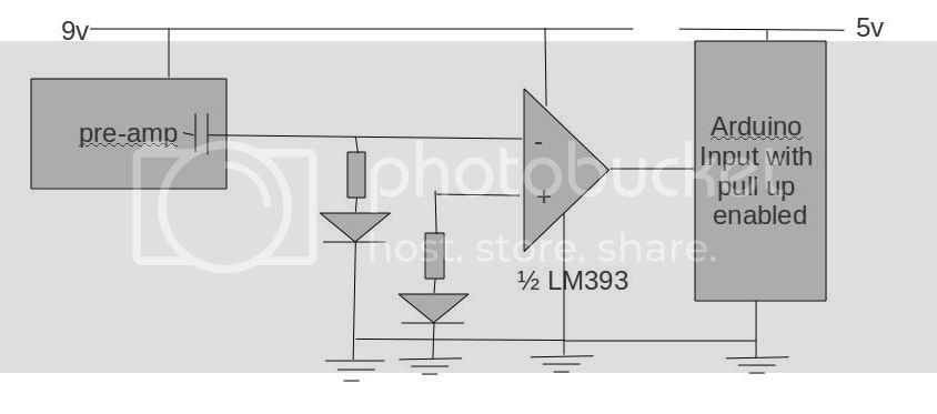
here is what I have now. it shows one arduino pin being served.
I have another cricuit just like it servicing another arduino pin.
the pre-amps are earthed too, but I forgot to draw that line.
since the LM393 is open collector, I can connect the
5V arduino to this 9V setup.