Regulating 120Vac w/Arduino - noob questions

It's like people don't even read what you write, frustrating when you explain what you want several times and people still don't read it.

Yup, totally true - as I said before this works great with the old-school dimmer I'm using now so I'm simply trying to replicate that - and honestly to use this to learn more about all this stuff. As I have a specific problem I'm trying to solve I'd like to solve that before switching to doing something different.

As I said I'll be using rather small desk fans so 1: unlikely I'll fry anything and 2: if I do all this is very inexpensive and I'll learn from it.

Thanks very much for the link, I'll give that a watch next. When you say "complete module" what exactly do you mean? Is that different than this unit I ordered from Amazon, which seems to do exactly what I want:

https://www.amazon.com/Light-Dimmer-Module-Arduino-Raspberry/dp/B06Y1DT1WP

Thanks again for the input guys, hopefully we've put the 12V/DC 120/AC conversation to bed as again I fully understand the pros and cons of each, in my specific use case I want 120vac.

1 Like

this module seems extremely dangerous, even though it is complete with two optocouplers and airgap for voltage isolation

However after browsing the web for something similar I can say that the module you found have the highest amount of components (e.g. snubber circuit) so it's probably the best of the lot
However, I suggest this "variation" found in suggestions instead
https://www.amazon.com/dp/B076V2RD26/ref=sspa_dk_hqp_detail_aax_0?psc=1
because it have a heatsink on the powerFET which help dissipate heat
even though the heatsink will likely be at line voltage when powered

But if you already have the blue unit ordered you can .. well, stick with it because it will likely perform well enough

Do you have a IR thermometer? I am worried about the potential for that powerFET to become so hot it will de-solder itself (among many other components for the snubber circuit)

If you do design a enclosure for it, find a place for like a computer case fan to blow air at the board.

Can you be more specific? In what way? Looking at the reviews between the two (which could be telling or not) the one I listed has nothing but great reviews, the one you listed doesn't - not arguing as I can easily enough cancel the first one and order this one, in fact I may do that just due to the shipping times as the one I ordered is weeks out and yours seems to be in stock.

And yes, I have an IR thermometer so I can monitor that pretty easily.

As I'm realizing how new I am to just controlling the Ardunio I ordered a "starter kit" with a ton of stuff so I can start by doing simple control before moving on to controlling the voltage regulator. I have a few other projects in mind I'd like to build and learn with so I realized that starting there with some basic projects is likely the smart call.

Thanks again for the input!

~Ross

1 Like

The way that all line-voltage traces are not covered in epoxy or other materials to prevent the user from electrocuting themselves by touching the board

In an actual product (e.g. power supplies for desktop computers), there will be cases/shielding so a user will be next to impossible to get electrocuted when operating the whatever it is.

We all know a bare PCB is not a complete product, yet it is sold as-is and thus should do as much to prevent users from electrocuting themselves as possible

But said epoxy shielding may impede cooling (and increase cost) or for whatever unimportant reason and thus it is absent

And also, the aforementioned overheating issue. designer just casually used a surface mount because it is simpler for manufacturing (surface mount can be done by machines very easily whereas through-hole must be either manually done or require jigs)

He did use a "thermal-pad" area for the base for the powerFET, which will help but likely is insufficient.

The one I listed might not have much review-wise but the two circuit appears identical -- literally, the two large resistors have the same value!
Some of the small 3303 resistors are replaced by 334s but they should also have the same values (330 * 10 ^ 3 vs 33* 10^4)

No my link was the same but inferior. I think you found probably the best solution :slight_smile: All you need now is a housing and A/C receptacle. Search for "plastic hobby box" or similar.

If you want to test the board out before putting it in a box, find an old extension cord you can sacrifice for your project, cut it in the middle and use one end for the fan and the other for power.

As for:

It's like people don't even read what you write, frustrating when you explain what you want several times and people still don't read it.

You have to understand the folks here see "noob and mains voltage" are likely to suggest a "safer" avenue. I've seen folks trying to work with 480 VAC and an Arduino. Often they don't understand the scope of what they are doing. So don't be offended.
Also, these folks are trying to help and give you their opinion. If you don't like the opinion just ignore it.

2 Likes

Yeah, do that! :rofl:

Now by the way, note that "small desktop fans" generally already incorporate stepped speed control, so are controllable. They use either taps on the windings or series (AC rated) capacitors to control speed.

Using phase control on fans tends to cause a noticeable buzz which would be annoying if the fan is just for cooling but in the application described here, I doubt that will be a problem. :grin: It sounds like it will need to be not too small a fan though.

The Robotdyn modules referenced in #2 look like the best option.

1 Like

I went back and had another look…
Couldn’t see any reason a high volume DC fan was unsuitable.

You might be smarter than everyone else here, but it looks like the easiest, cleanest solutions just won’t work for you.

The dog will thank you.

It's for your benefit, don't fool around with mains supply.
There, said it again.

Hmm, I don't know how you missed my first post as this seems VERY clear

My goal is to make this as simple as possible in that you'd plug an existing small fan into the device rather than using a custom fan/enclosure.

By "plug in" I mean plug in a 120vac desk fan (like I said later on). Never once said, implied nor meant that I'm smarter than anyone here - in fact the reason I'm here is that I'm absolutely not. But getting solutions that don't fit my problem aren't solutions at all, especially when I've had to address this like 4-5 times. I understand 12v DC is safer but I can be PERFECTLY SAFE using 120vac - as well my dog Daisy (and the rest of my family). Respecting 120vac is one thing, being terrified of it like it's nuclear waste is getting absurd. So if you'd like to build your own wind simulator awesome, go right ahead and use 12v fans, build custom housings, run ducting, etc. etc. That's not what my project is, at all.

It was helpful and appreciated the first time. It was even appreciated the second time. Now that we're at the 5th-6th+ time it's getting annoying.

Okay sweet, and yup, I already got a small "hobby box" for this project so everything will be enclosed nice and safe in there. Nothing will get touched, shorted, etc. etc. Just like the 20+ other devices I have plugged into 120vac at my sim rig.

Thanks for the specifics, I get what you mean now, this is good to know. As I've said I'll be building in a small project/hobby box so nothing is going to get touched, shorted or dead.

I have a really small fan (like 30 or 40mm) that I may build into the side of the box just to be safe. I'll check the temps and see if that's needed or not - it will be in a somewhat enclosed space behind my sim rig so either way I'll make sure it has good ventilation.

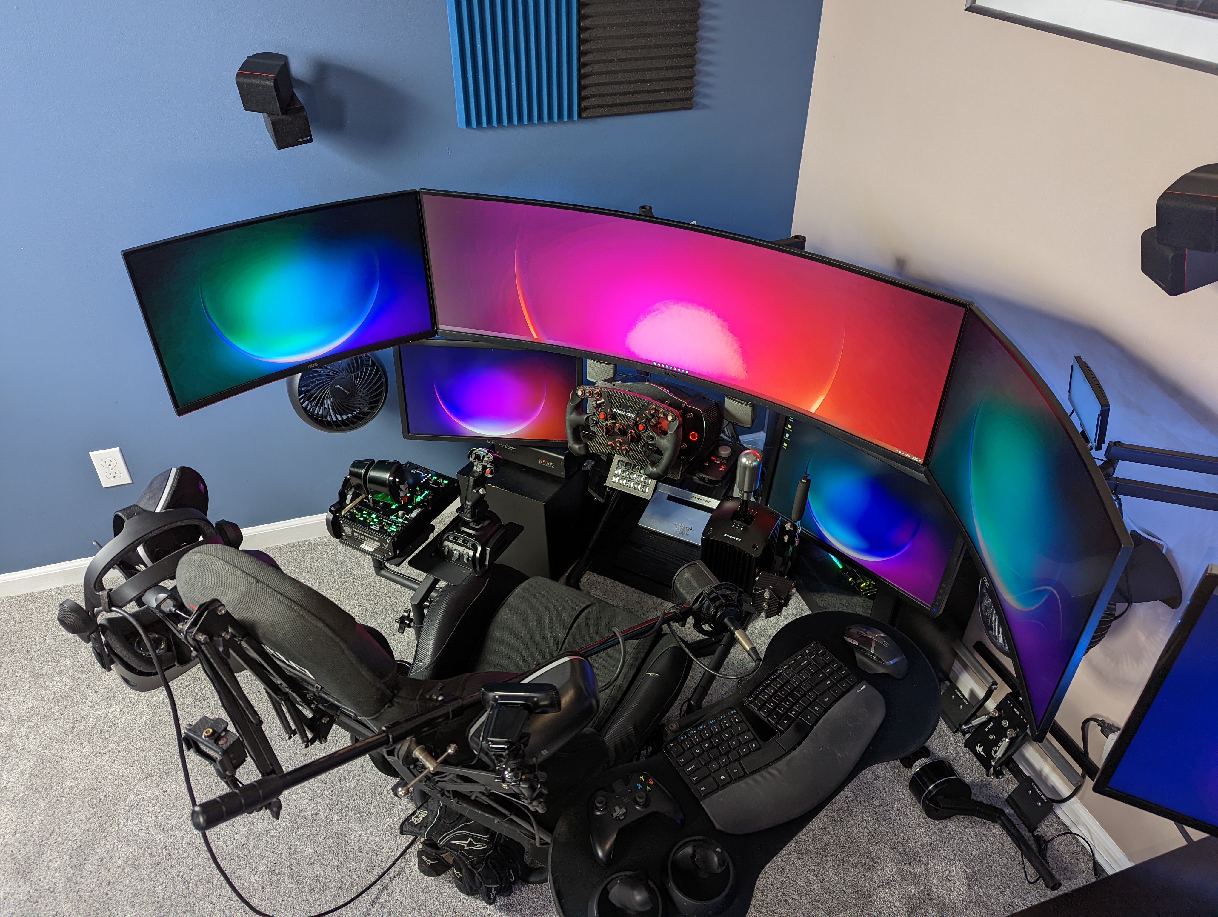
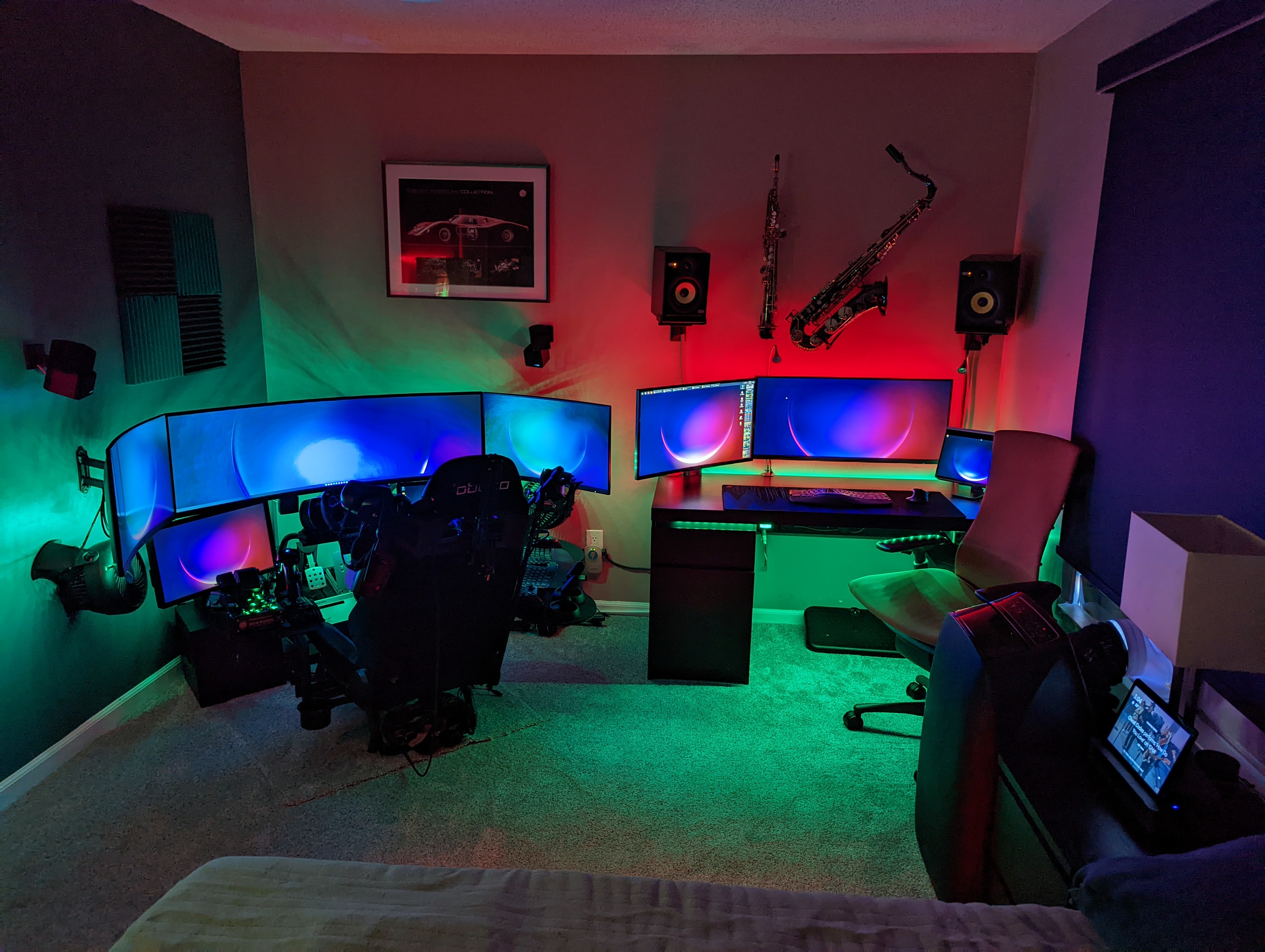
For context and to help understand why I'm using 120vac fans here is a picture of my sim setup. You'll see the 2 fans flanking both sides just under the outer monitors. Those are what will be controlled, it would be rather difficult given my space constraints to go with ducted 12v fans.

Thanks one last time for the concern, hopefully for the last time I can assure you it's well taken and I'll have zero issues. Mostly thanks for all the information, I'm looking forward to my starter kit showing up so I can build some really simple stuff before jumping into this.

~Ross

No offence taken.
I can’t count the times I’ve seen ā€˜hackers’ trying to implement potentially dangerous solutions here.

It may be as simple as a misplaced elbow or loose jumper wire during construction.

We have to state our concerns. To ignore those would be negligent by responding without warnings.

Sorry, that tells us you really dont have enough respect for mains electricity!

It's called "solder mask" and it's not there for human safety to begin with. It's not applied to some traces so those can be flooded with tin to create a bigger conductor with a higher current carrying capacity. This prevent the user from burning their house down etc.

There is no FET on that board.
The triac / thyristor isn't likely to get hot at the load of a typical desktop fan (<100W) as long as the module is halfway decently decently designed, which it's likely to be.

And they've been stated - over and over and over and over and over.... and I've acknowledged them over and over and over and over and over.

And this tells me you can't read, are completely dishonest and take quotes out of context. As if you actually READ THE THREAD you can see that yes, I know this is somewhat dangerous, yes I know what I'm doing with electricity and yes, I take this seriously - THAT is why I don't have any concerns for my safety. I guess I was wrong about this community being toxic, at least a few key members like yourself.

And once again you prove to be a great resource and extremely helpful, once again I say thank you. At this point I think I'm done with this thread as I've gotten exactly what I need from it and will have other things to learn before I step into this part of the project. I'll certainly be back in the future and will look forward to massive condescension from a minority and help from the majority.

Thanks again to those who were helpful!

~Ross

I'm referring to the additional layer of epoxy on top of the finished PCB. It's usually a "flood fill" into the product/case but it can also be done in a mold so the PCB can be taken out later
You will see that on certain high-voltage boards (e.g. water heater main board), boards that might be working in humid conditions (e.g. secondary under-sink controller), or boards that contain high-power circuitry (e.g. Dyson Battery Pack)
Like this
image

.. ok not epoxy. resin. not too different.
Except for the boards at my home the resin is see-thru

I don't think it is dangerous. The board is only dangerous because it has no insulation on the board. It has two optocoupler for total insulation and there are massive airgap to ensure the mains voltage will not jump across onto the controller lines. It is only "dangerous" because the dimmer might not work properly with a fan, but as he has tested earlier, it works with a traditional in-wall dimmer. Just make sure to have a sturdy box (recommended to purchase a plastic wiring box. they are cheap and sturdy).

Good luck on your project.

Ok, that's called "conformal coating" and like solder mask it primarily serves a technical function. In this case mostly protection against the elements, which is particularly relevant in high voltage circuits to prevent creepage. However, it's very unusual to apply this kind of coating to boards that intended to be part of regular equipment that will be used in a normal indoor environment (not excessively humid, subject to vibrations etc.)
Really, if a few basic safety precautions are taken, boards like these without additional coatings etc are perfectly safe to work with. Conversely, the presence of such a coating would by no means compensate for a lack of safety measures or awareness by the user - if you're stupid enough, you'll zap yourself anyway, bluntly said. I know I have over the years, and guess what, it would never have been prevented by a conformal pcb coating.

1 Like

@anon35827816 Just wanted to close the loop as I got the following module today, took me less than 15 minutes to have a proof of concept and another 30 or so to have it installed and working with my driving simulator

Amazon.com: PWM AC Light Dimmer Module 50Hz 60Hz For Arduino and Raspberry LED Smart Home : Electronics

I was shocked at how easy it was (see what I did there). And guess what, I didn't kill myself, burn my house down, injury my pets or otherwise have any of the other horrors from this thread befall me. It's almost like thousands of people every day work with 110AC very safely and I was one of those people. Go figure.

And I gotta say having the fans blow harder and harder as I'm driving faster and faster keeps making me giggle as it's just so damn cool. I've wanted to build this for years and can't believe how incredibly simple it was.

So thanks again for all the assistance from everyone, appreciated.

~Ross

1 Like

Only one thing left to say then......

:smiley:
I'm happy you're happy!

Continuing to be as unhelpful as ever I see, at least that was pretty funny.

Yup, I'm thrilled. Now to prototype a 3D printed enclosure, source connectors, etc. as I plan on making a limited run product of these. Have a few friends interested to help me test before that. Either way it's awesome, it's funny I was so unsure of Arduino all these years and figured it was something so complex I didn't have time to learn it - in less than 4 hours work I've built the two projects I've wanted forever.

So again thanks to you for your advice and input, it's very apprecaited.

~Ross

1 Like

I'm glad you found a way into this; it sure is a lot of fun (most of the time).