Hi @Wawa .
Thanks, you are right. I've already corrected it.
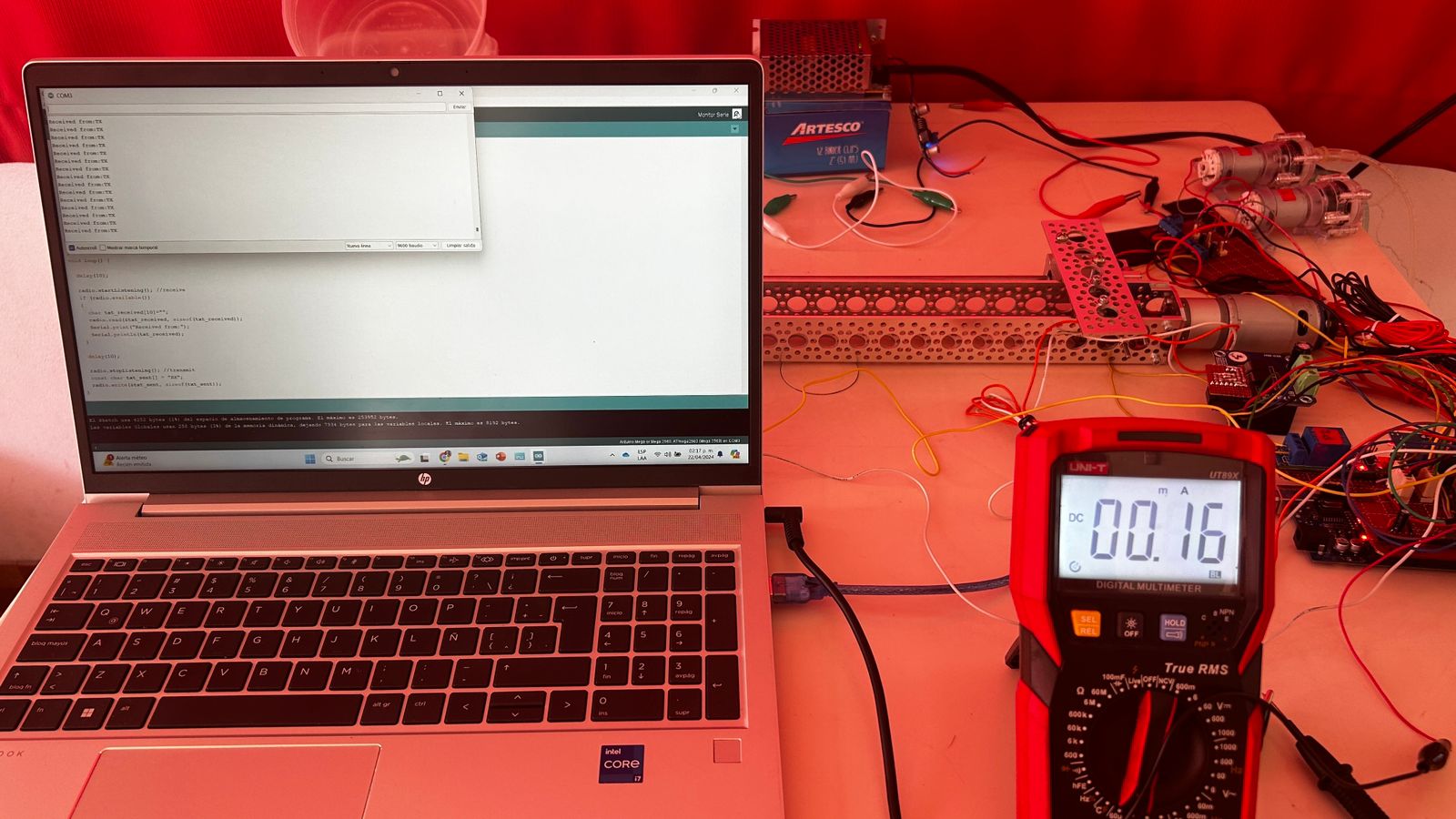
I replaced the Nano with another Mega, using its 3.3V and GND as the power supply, but the TX keeps displaying Message 2 with some message lines missing. I also ran a program that simply sent text TX->RX and RX->TX. Apparently it worked fine, except that in the serial monitor of the TX, the message from the RX wasn't displayed with the same fluidity as it was in the RX serial monitor.
Button 3 button rarely fails (you press it once, and temperature is displayed correctly on the TX serial monitor).
The other two, controlling the pumps, are the main issue (Button 1 and Button 2 keep the pumps running; releasing them stops the pumps). I've tested it with other buttons, and the same thing happens. Perhaps it's a coding issue.
COMPLETE CODES
TX CODE
//TRANSMITTER
#include <SPI.h>
#include <nRF24L01.h>
#include <RF24.h>
//PINS------------------------------------------------------------------------------------------------------------------------
// NRF24L01 Pins
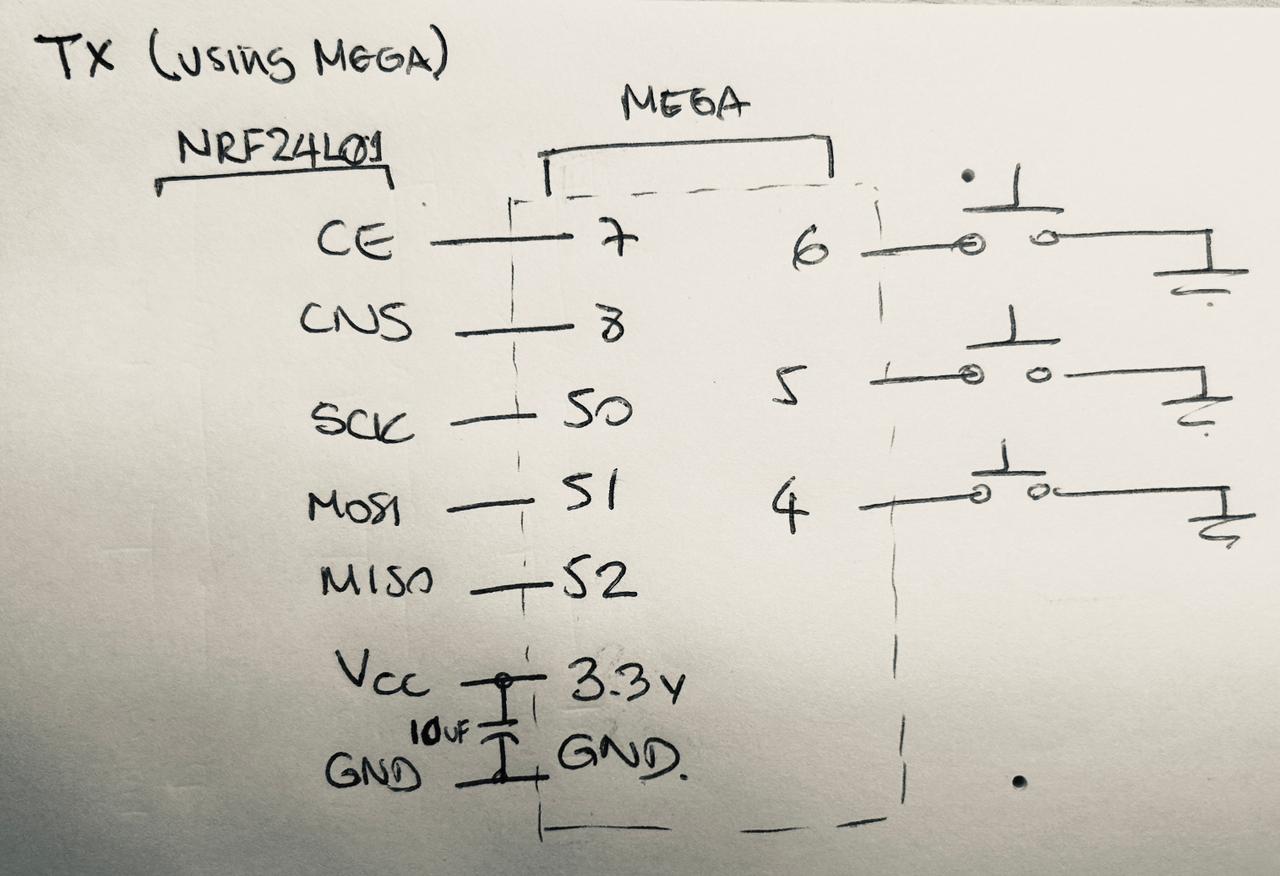
RF24 radio(7, 8); // CE, CSN
const byte address[][10] = {"00001","00002"};//addresses that receives and transfer data
// Pump Pins
const int Button1 = 6; //Controls Pump1
const int Button2 = 5; //Controls Pump2
// DS18B20 Pin
const int Button3 = 4; //Controls DS18B20
//VARIABLES------------------------------------------------------------------------------------------------------------------------
// NRF24L01 Variables
int Message1[3];
char Message2[50];
//MAIN------------------------------------------------------------------------------------------------------------------------
void setup() {
pinMode(Button1, INPUT_PULLUP); // Pump1 - Enable internal pull-up resistor for button
pinMode(Button2, INPUT_PULLUP); // Pump2 - Enable internal pull-up resistor for button
pinMode(Button3, INPUT_PULLUP); // DS18B20
Serial.begin(9600);
radio.begin();
radio.openWritingPipe(address[0]);//address of transmitter
radio.openReadingPipe(1, address[1]);//address of receiver - specify the ch-freq in which receives
radio.setPALevel(RF24_PA_MAX);//set power amplifier level
delay(10);
}
void loop() {
delay(10);
radio.stopListening(); //transmit
Message1[0] = digitalRead(Button1); // Pump1 button current state
Message1[1] = digitalRead(Button2); // Pump2 button current state
Message1[2] = digitalRead(Button3); // DS18B20
radio.write(Message1, sizeof(Message1));
radio.startListening(); //receive
if (radio.available())
{
// Read data into the Message2 array
radio.read(&Message2, sizeof(Message2)); // Correct usage for arrays
Serial.println(Message2);
}
}
RX CODE
#include <SPI.h>
#include <nRF24L01.h>
#include <RF24.h>
#include <OneWire.h>
#include <DallasTemperature.h>
#include "BTS7960.h"
//TIMERS ()-----------------------------------------------------------------------------------------------------------------
#define BUTTON_STATE_CHECK_INTERVAL 10 // Check button state every 10 milliseconds
#define TEMP_READ_INTERVAL 1000 // Read temperature every 1 second
//PINS AND PIPES---------------------------------------------------------------------------------------------------------------
// NFR24L01 Pins
RF24 radio(7, 8); // CE, CSN
const byte address[][10] = {"00001","00002"};//addresses that receives and transfer data
// Pump Pins
const int pinRelay1 = 9;
const int pinRelay2 = 10;
// DS18B20 Pins
#define ONE_WIRE_BUS 24 // Data wire is plugged into pin 25 on the Arduino
//VARIABLES------------------------------------------------------------------------------------------------------------------------
// NRF24L01 Variables
int Message1[3];
char Message2[50];
// Pump Variables
bool previousButtonState1 = HIGH; // Variable to store the previous state of the button. Initially high (not pressed)
bool previousButtonState2 = HIGH; // Variable to store the previous state of the button. Initially high (not pressed)
bool printedState = false; // Flag to control the printing of the state
enum State1 {OFF1,ON1}; // States of Pump1
enum State2 {OFF2,ON2}; // States of Pump2
State1 state1 = OFF1;
State2 state2 = OFF2;
State1 previousState1 = OFF1;
State2 previousState2 = OFF2;
// DS18B20 Variables
unsigned long lastDebounceTime = 0; // debounce timer for Button 3
const unsigned long debounceDelay = 1000; //milliseconds
unsigned long lastTempReadTime = 0;
enum State3 {OFF3, ON3};
State3 state3 = OFF3;
int buttonState3; //button for temperature sensor DS18B20
//FUNCTIONS---------------------------------------------------------------------------------------------------------------------
// Pump Functions
void turnonPump1();
void turnoffPump1();
void turnonPump2();
void turnoffPump2();
// DS18B20 Functions
void readtemperature();
//OBJECTS------------------------------------------------------------------------------------------------------------------------
// DS18B20 Objects
OneWire oneWire(ONE_WIRE_BUS); // Setup a oneWire instance to communicate with any OneWire devices
DallasTemperature sensors(&oneWire); // Pass our oneWire reference to Dallas Temperature.
//MAIN------------------------------------------------------------------------------------------------------------------------
void setup() {
pinMode(pinRelay1, OUTPUT); // Initialize relay pin as output
pinMode(pinRelay2, OUTPUT); // Initialize relay pin as output
turnoffPump1();// Pump1 initially off
turnoffPump2();// Pump2 initially off
Serial.begin(9600);
radio.begin();
radio.openWritingPipe(address[1]);//address of transmitter
radio.openReadingPipe(1, address[0]);//address of receiver - specify the ch-freq in which receives
radio.setPALevel(RF24_PA_MAX);//set power amplifier level (minimum since NRFs are close)
sensors.begin(); // DS18B20
}
void loop() {
unsigned long currentTime = millis();
unsigned long lastButtonStateCheckTime = 0;
// Check button state at regular intervals
if (currentTime - lastButtonStateCheckTime >= BUTTON_STATE_CHECK_INTERVAL) {
lastButtonStateCheckTime = currentTime;
radio.startListening(); // Start listening for radio messages
if (radio.available())
{
radio.read(Message1, sizeof(Message1));
int buttonState1 = Message1[0]; // Pump1 button current state
int buttonState2 = Message1[1]; // Pump2 button current state
int buttonState3 = Message1[2]; // DS18B20 button current state
// Pump1 Control
if (buttonState1 != previousButtonState1) { //Compare previous and current states of the button1
if (buttonState1 == LOW) { //keep the button1 activated
turnonPump1(); // Turn on Pump1
state1 = ON1;
} else {
turnoffPump1(); // Turn off Pump1
state1 = OFF1;
}
previousButtonState1 = buttonState1; // Update previous button state for button 1
}
// Pump2 Control
if (buttonState2 != previousButtonState2) { //Compare previous and current states of the button2
if (buttonState2 == LOW) { //keep the button2 activated
turnonPump2(); // Turn on Pump2
state2 = ON2;
} else {
turnoffPump2(); // Turn off Pump2
state2 = OFF2;
}
previousButtonState2 = buttonState2; // Update previous button state for button 2
}
// DS18B20 Control
if ((currentTime - lastTempReadTime) >= TEMP_READ_INTERVAL && buttonState3 == LOW && (currentTime - lastDebounceTime >= debounceDelay)) {
readtemperature(); //Read temperatures from DS18B20 sensors
state3 = ON3;
lastDebounceTime = millis(); // Update debounce timer
} else {
state3 = OFF3;
}
}
}
delay(10); //Wait a short time before switching from listening to transmitting (avoid interference)
radio.stopListening(); //transmit
if (state1 != previousState1) { //Compare previous and current states of the button1
switch (state1) {
case OFF1:
strcpy(Message2, "PUMP 1 OFF");
radio.write(&Message2, sizeof(Message2));
Serial.println(Message2); //TEST
break;
case ON1:
strcpy(Message2, "PUMP 1 ON");
radio.write(&Message2, sizeof(Message2));
Serial.println(Message2); //TEST
break;
}
previousState1 = state1; //update state1
}
if (state2 != previousState2) { //Compare previous and current states of the button2
switch (state2) {
case OFF2:
strcpy(Message2, "PUMP 2 OFF");
radio.write(&Message2, sizeof(Message2));
Serial.println(Message2); //TEST
break;
case ON2:
strcpy(Message2, "PUMP 2 ON");
radio.write(&Message2, sizeof(Message2));
Serial.println(Message2); //TEST
break;
}
previousState2 = state2; //update state2
}
  if (state3 == ON3) { //Compare previous and current states of the button3

    //Read temperatures
    float temp1 = sensors.getTempCByIndex(0);
    float temp2 = sensors.getTempCByIndex(1);

    // Crear cadenas para las temperaturas
    char tempStr1[20];
    char tempStr2[20];

    // Formatear temperaturas en cadenas
    dtostrf(temp1, 4, 2, tempStr1);
    dtostrf(temp2, 4, 2, tempStr2);

    // Construir el mensaje
    sprintf(Message2, "T1: %sC\nT2: %sC", tempStr1, tempStr2);

    radio.write(&Message2, sizeof(Message2));
    Serial.println(Message2);//TEST
  }
}
//FUNCTIONS------------------------------------------------------------------------------------------------------------------------
void turnonPump1() {
digitalWrite(pinRelay1, LOW);
}
void turnoffPump1() {
digitalWrite(pinRelay1, HIGH);
}
void turnonPump2() {
digitalWrite(pinRelay2, LOW);
}
void turnoffPump2() {
digitalWrite(pinRelay2, HIGH);
}
void readtemperature(){
sensors.requestTemperatures(); // Send the command to get temperatures
}