Hi
I have a solar panel I like to messure volt with an esp32.
Max input is 3,3V
Solar max 6,2V
How do I calculate the R2 in the voltage divider when R1=Solar ?
Hi
I have a solar panel I like to messure volt with an esp32.
Max input is 3,3V
Solar max 6,2V
How do I calculate the R2 in the voltage divider when R1=Solar ?
Try this link:-
Nice grumpyMike, but I dont know R1...
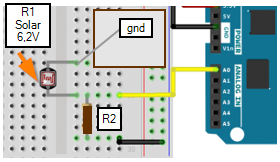
Im familiar with this:
![]()
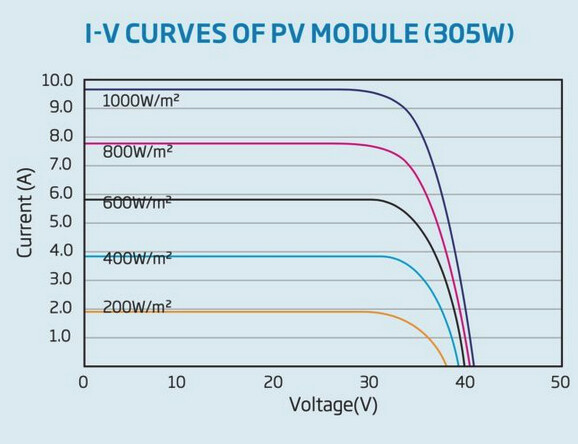
A solar panel is not a resistor.
Yes, that makes sense. Then, is there a way to measure the solar volt from this 6,2V solar when ESP32 only handle 3,3V?
Use the formula you supplied:
Pick R1 as you please; e.g. 22k or so.
Apply a safety margin for the voltage; e.g. if your solar panel puts out 6.2V, make Vin 50% larger, so around 9.5V. This way you won't use the entire range of the ESP's ADC, but the input will at least not exceed the maximum ratings of the ESP.
R1 can be any value of resistor going to your solar panel and R2. It dictates the overall current (along with R2). I would use 10K, but it can be anything.
<10 ohm and >100k highly not recommended ![]()
What are you trying to do. Panel voltage on it's own is meaningless.
I would be more interested in battery voltage, or solar current.
Leo..
Out of your question, but if your intention is to sense solar intensity or production of that panel, voltage is not going to give that. What you can sense is presence of sun.
If you pick suitable values for the resistors so they draw a sensible current you will get an idea of the output.
Hi
thanks for input!
Solved for my purpose.
The ide is to measure values that changes in 24h, so then I can send lora pakages more frequent in sun, less when dark (day/night). Also prioritize charging of power supply; supercap vs LiPo.
In Norway it is 5h daylight in Desember, so this is to avoid running around and change batteries in winter time / snow.
I used 2 x 1kOhm, power from fixed supply 6.2V I read 3.0 volt.
Now I connect this system to my monitor system and fins a graph.
FYI.
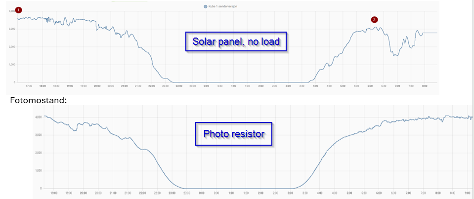
I tested with a photo resistor yesterday, but I plan to use existing solar panel and not add another component to system (out of gpios):
M
Basically the solar panel converts solar intensity to current (its basically a constant voltage source); and the voltage is mostly dependent on the temperature. Maybe you best stay with the photoresistor?
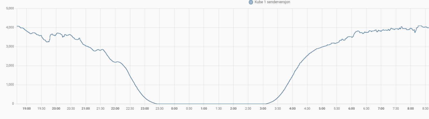
This may be true, but I experience when not add load to solar it starts in sun like 6V, then goes down to 3v when shade, and to 0,2 when early evening. In real when connected to the system it will charge the supercap or LiPo, ie. a load.
I will hook it up to my system to get a graphical presentation (as for photo conductor) and see if I can corelate the solar voltage output to the photo resistor voltage readings.
My biggest issue is my ESP32 WROOM is out of GPIO/GPI pins, so I really want to do solar volt readings to determine night/day, not add another component.
Minus -10 Celsius I can not charge LiPo, only super cap, a not too big super capacitor 5-10F, and I need it to be powered by solar in winter time. I will appreciate any idea!!!
Here is my main tread for my project
Yes if you are looking at the open circuit voltage it will change a bit with intensity.
And the difference in intensity between full bright sun and dark shade is HUGE
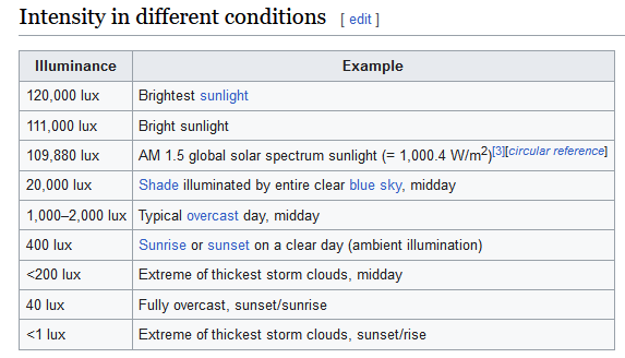
HI, thanks for info. here is the solar panel curve and photo resistor
NB not same conditions, but both days pretty nice and sunny
This may be stupid but what if a PV panel is connected to a DC boost converter to 12V or more to feed a charger?
H
I have solar connected to a charging circuit. My system charge a LiPo and from there has a 3,3V and 5V rail on PCB.
This topic was automatically closed 180 days after the last reply. New replies are no longer allowed.