"rising" interrupts behaves as "chance" on mega2560

hi everyone,
i have been useing nano and uno for long time, but their pins and storages not enought for last project.
So i was moved to mega2560.

my trouble; attachInterrupt(0, say, RISING); command works good on arduino nano,
but not working correctly on mega.

normally(rally normal on nano) ;RISING to trigger when the pin goes from low to high.
when the pin voltage 0 to 2,4 , interrupt function called only one time and sayi increase +1
if pin voltage is 5 to 0 , no chance anything.

but the same codes upload to mega2560
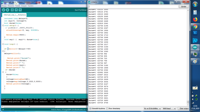
when the pin voltage is between 1,5 - 2,4 ,interrupt function is looping and "sayi" increasing limitless .

i need rising or falling function four interrupt pins.
Regards...

unsigned long delays=0;
int sayi=0, voltage=0;
bool durum=false;
void setup() {
// pinMode(2 ,INPUT_PULLUP);
attachInterrupt(0, say, RISING);

Serial.begin(9600);
}
void say() { sayi++; durum=true;}

void loop() {

if ((millis()-delays)>=50)
{
delays=millis();

Serial.print("durum=");
Serial.print(durum);
Serial.print(" ");
Serial.print(sayi);
Serial.print(" ");
if (durum)
{
durum=false;
}
voltage=analogRead(A0);
voltage=map(voltage,0,1023,0,5000);
Serial.println(voltage);
}
}
thats on nano, shows (durum,sayi,voltage) on serial monitor

thats on mega2560, shows same
sayi and durum have to be declared volatile. You didn't do this, and that may cause unpredictable behaviour.

2.4V is a very low voltage to expect a HIGH on a 5V Arduino. Normally HIGH is guaranteed at voltages higher than 0.5Vcc or even 0.7Vcc (check the data sheet). So that'd be 2.5V or even 3.5V. Your 2.4V is not high enough.

Do some signal conditioning to bring your 2.4V up to 5V. An OpAmp with 2x gain or a comparator are two options for this.

wvmarle:
sayi and durum have to be declared volatile. You didn't do this, and that may cause unpredictable behaviour.

2.4V is a very low voltage to expect a HIGH on a 5V Arduino. Normally HIGH is guaranteed at voltages higher than 0.5Vcc or even 0.7Vcc (check the data sheet). So that'd be 2.5V or even 3.5V. Your 2.4V is not high enough.

Do some signal conditioning to bring your 2.4V up to 5V. An OpAmp with 2x gain or a comparator are two options for this.

my signal volume is 0-3,8v (you can see picture) and arduino 5v chips accept 1,5v to 3.0v low to high

main problem "rising interrupt" didn't work as "rising interrupt" on mega2560
its working as "change interrupt"

Do check which pins on the Mega support "external interrupts" and connect the appropriate interrupt for that pin.

wvmarle:
Do check which pins on the Mega support "external interrupts" and connect the appropriate interrupt for that pin.

i tried to find rising support on datasheet(110st page), i understand that support rising edge all external interrupts
and i used pin2 for int0 on mega or nano, (not wrong pin)

Of course.

Do mind that the pinout of the ATmega2560 is not the same as that of the ATmega328. Make sure those interrupts connect to the pins you think they do.

It's one of the points where code is not always compatible, especially as you didn't use the digitalPinToInterrupt() function.

nano and mega have the same pin number for int0 and int1

mega has additional int2,int3,int4,int5

i used int0

This is not the best way to call attachInterrupt.

  attachInterrupt(0, say, RISING);

when the pin voltage is between 1,5 - 2,4 ,interrupt function is looping and "sayi" increasing limitless .

This is not a valid logic level when Vcc=5V.

jremington:
This is not the best way to call attachInterrupt.

  attachInterrupt(0, say, RISING);

This is not a valid logic level when Vcc=5V.

i changed code but nothing chances

attachInterrupt(digitalPinToInterrupt(2), say, RISING);

You still have a voltage level problem. Fix it.

ok i t

jremington:
You still have a voltage level problem. Fix it.

ok i tried a 10k pot
pot connectted as voltage divider (gnd, pin2, vcc)

results:

if pin2 voltage 0v to 5v interrupt called (voltage goes up)
when pin2 voltage is 2,3v , interrupt goes looping
when pin2 voltage is 2,5v , interrupt goes "0"

if pin2 voltage 5v to 0v interrupt called (voltage goes down)
when pin2 voltage is 2,5v , interrupt goes looping
when pin2 voltage is 2,3v , interrupt goes "0"

shortly if pin2 voltage between 2,3v-2,5v interrupt goes looping

i want:
normally (on try 328p chip) if voltage is 0v to 5v , interrupt called only one times(not looping)
if voltage 5v to 0v , interrupt not called.

2.5V is not a valid logic level, and cannot be used to trigger an interrupt.

You need an amplifier on the input to ensure a 0 to 5V transition (or 5V to 0V). A simple, single stage transistor amplifier should do the job.

im already used 5v by 10k pot as voltage divider.
i tried again
and plotted interrupt function change according to the pin2 voltage
two test made

blue: interrupt function
red : pin2 voltage
on arduino nano

if voltage goes up the interrupt called only one times(when voltage level reached 2,5v)

blue: interrupt function
red : pin2 voltage
on arduino mega

if voltage between 2,3v to 2,5v interrupt goes looping and blue line high

codes

unsigned long delays=0;
int sayi=0, voltage=0,durum2=0;
bool durum=false;
void setup() {
 // pinMode(2 ,INPUT_PULLUP);
  attachInterrupt(digitalPinToInterrupt(2), say, RISING);

  Serial.begin(9600);
}
void say() {  sayi++; durum=true;}

void loop() {

if ((millis()-delays)>=50)
{    
delays=millis();

  // Serial.print("durum=");


 if (durum)
 { 
  durum=false; 
  durum2=5000;
    Serial.print(durum2);
  Serial.print(" ");
  }
  else{
    durum2=1000;
      Serial.print(durum2);
  Serial.print(" ");}
  voltage=analogRead(A0);
  voltage=map(voltage,0,1023,0,5000);
  Serial.println(voltage);
}
}

jremington:
2.5V is not a valid logic level, and cannot be used to trigger an interrupt.

The pins are supposedly equipped with Schmitt triggers that prevent exactly this kind of behaviour. Go high when the voltage goes >0.5Vcc, go low when it goes <0.3Vcc.

The pins are supposedly equipped with Schmitt triggers

That is certainly true on some MPUs, but the ATmega2560 data sheet is surprisingly silent on this issue.

The data sheet gives no details other than to state in Table 31.7 "Hysteresis of Schmitt Trigger Inputs 0.05 VCC"

I will continue to maintain that 2.5V is not a valid logic level for a 5V processor, and cite the OP's own experiments as evidence in favor of that statement.

The analog comparator (tutorial) can be used to circumvent the OP's problem for one input signal.

Interesting, didn't expect that.

In one of my projects I'm making active use of this: timing the discharge of a capacitor, trigger interrupt when it falls below or rises above the pin threshold. A very stable value for each individual pin on the ATmega328p, ESP8266 and ATtiny841. The '84 and '85 I remember testing as well and behaving the same.

Never tried the Mega2560, don't have them in my parts kit, never needed them. It's by the way also the only processor in the AVR family that I'm aware of that needs at least 4.5V to operate making it a bit of an oddball.

Absolutely, digital inputs normally will generate some/many/thousands of spurious transistions if
presented with a slowly varying analog voltage, and also will consume far more power than normal
as both input transistors are half-on, leaking a few mA direct to ground though the input stage.

This is why digital inputs are connected to digital sources! Typical logic inputs expect slew rates of
at least 1--10V/us to behave properly.

With proper schmitt-trigger inputs you don't have to worry about this, but many microcontrollers
have weak-schmitt-triggers with a few 100mV of hysterysis - better than nothing, but not much
noise immunity compared to a 74HC14 for instance.

I suspect there's hidden high frequency noise on the signal not seen in the graphs, which is why the
circuit flips at random.

MarkT:
Absolutely, digital inputs normally will generate some/many/thousands of spurious transistions if
presented with a slowly varying analog voltage, and also will consume far more power than normal
as both input transistors are half-on, leaking a few mA direct to ground though the input stage.

This is why digital inputs are connected to digital sources! Typical logic inputs expect slew rates of
at least 1--10V/us to behave properly.

With proper schmitt-trigger inputs you don't have to worry about this, but many microcontrollers
have weak-schmitt-triggers with a few 100mV of hysterysis - better than nothing, but not much
noise immunity compared to a 74HC14 for instance.

I suspect there's hidden high frequency noise on the signal not seen in the graphs, which is why the
circuit flips at random.

Unfortunately I thought it and used capasitor 10uF gnd to pin2 results is the same
(200nF capasitor used last graphics)

i was solved problem transiently how i change codes. But it slows down the main process.
i will use it for now. I think the chip is faulty

unsigned long delays=0;
int sayi=0, voltage=0,durum2=0;
static bool durum=false,isr0=true;

void setup() {
Serial.begin(9600);
}
void say() {   detachInterrupt(digitalPinToInterrupt(2));
isr0=true;
if(analogRead(A0)>400){  sayi++; durum=true;}
}

void loop() {
if (durum3==true){if(analogRead(A0)<300){ isr0=false; attachInterrupt(digitalPinToInterrupt(2), say, RISING);}}

if ((millis()-delays)>=50)
{    
delays=millis();

  // Serial.print("durum=");


 if (durum)
 { 
  durum=false; 
  durum2=5000;
    Serial.print(durum2);
  Serial.print(" ");
  }
  else{
    durum2=1000;
      Serial.print(durum2);
  Serial.print(" ");}
  voltage=analogRead(A0);
  Serial.println(voltage);
}
}

gursoytek:
Unfortunately I thought it and used capasitor 10uF gnd to pin2 results is the same
(200nF capasitor used last graphics)

Small ceramic caps are generally much better at filtering noise than large electrolytics. The 200 nF should take care of most high frequency noise.

i was solved problem transiently how i change codes. But it slows down the main process.

That does defeat the whole purpose of using interrupts... For fastest reaction, set the ADC in free running mode, triggering an interrupt every time there's a new reading, and then you can use that for your process.

i will use it for now. I think the chip is faulty

And I think that you don't understand what MarkT wrote.

I think the chip is faulty

No, it is working as well as expected.