They're likely long enough to be causing you trouble.
What's inside the power supply?
Is the red wire connected to the 12V bolt providing power or drawing power?
You want to minimize the amount of wire in your circuit. You should keep enough so things don't get pulled tight but all that extra wire causes problem.
You should probably add some large caps to the breadboard's power rails.
Powering lots of servos is a challenge. Some people say you shouldn't power servos from a breadboard. I sort of agree with these people but if the servo's aren't drawing a lot of current you can usually get away with using a breadboard.
Some sort of perf board with nice power distribution lines would be a better solution.
The power supply is out of an old computer. There is nothing inside the wooded box, it's just a housing to hold the terminals (bolts) and OI switch.
The red wire is drawing off a separate 12v line to the arduino (they're not internally or externally connected).
I series 3 x 2.7v 1F super caps and paralleled those to the 5v servo line and arduino ground. I think that did help.
If I power up the mega first then connect the power to the servo after the mega has booted it seems to work ok, but if I hit the power switch with everything connected at once it has a seizure.
Once it's all finished I'll transfer everything over to a perf board. I just need to finish off the turn table and add a second servo to the main boom arm, because one hasn't quite got enough lift when the arm is fully extended.
gyrojeremy:
I series 3 x 2.7v 1F super caps and paralleled those to the 5v servo line and arduino ground. I think that did help.
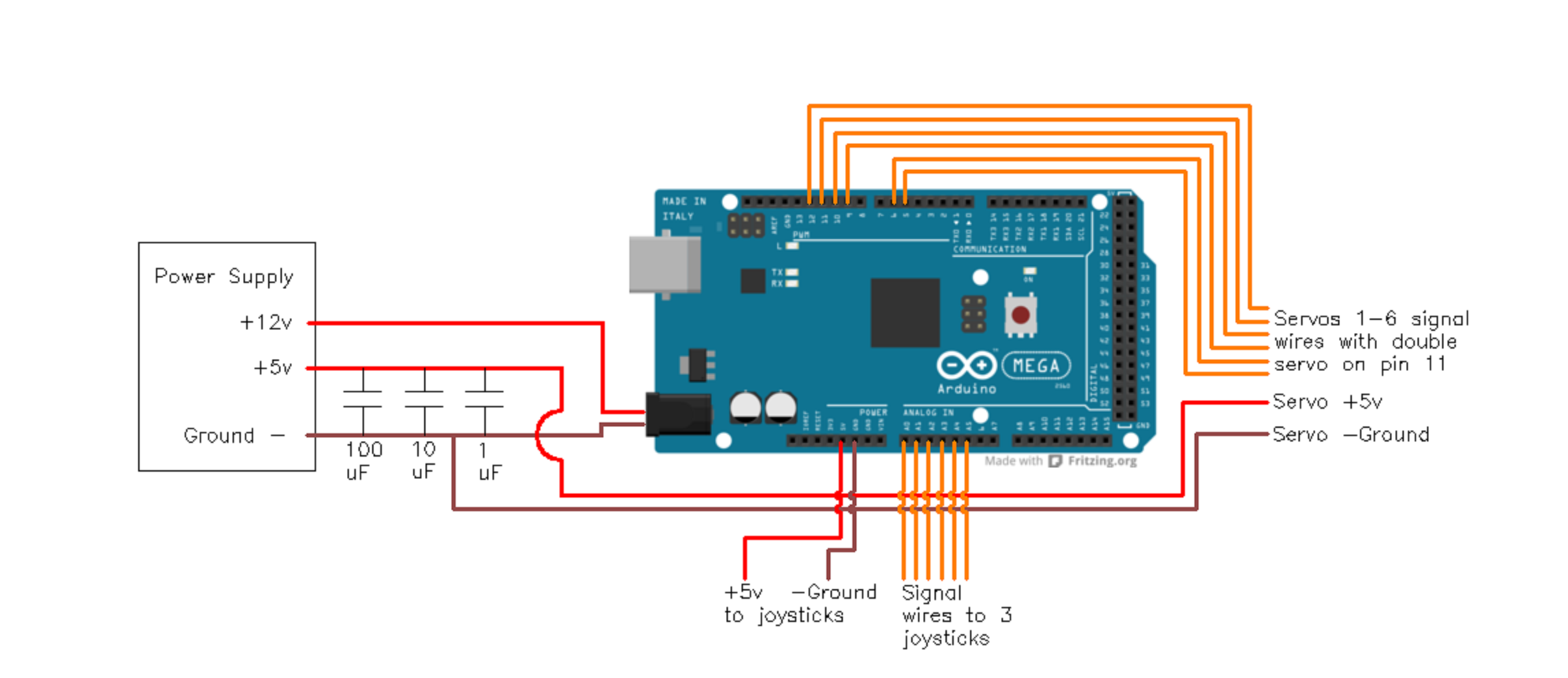
I was thinking of something like a 1,000uF cap and probably a couple other (smaller) sizes. Smaller caps can deliver their power faster than larger caps. I'd suggest adding 100uF, 10uF and 0.1uF caps. Add the caps close to the servos' power lines. Trim the leads of the caps so they're not longer than needed to fit in the breadboard.
Use shorter wire.
I've modified my joystick/servo control code again. I added a constant acceleration component so the servos don't try to start moving at full speed. I'll post this new code sometime soon.
"Smaller caps can deliver their power faster than larger caps."
A big part of that is their internal resistance also. Parts with low ESR can put out more current faster - with large capacitance tho, you have to watch out for large inrush current when power is first applied, and plan your design to account for that. http://www.digikey.com/product-search/en/capacitors/electric-double-layer-capacitors-supercaps/131084?k=supercap
I did a design where I used a resistor to limit inrush current (took longer to charge up, but did not overwhelm the 5V regulator), diodes to prevent capacitor current from backfeeding into the source when incoming power was lost, and a boost regulator to hold the 5V line up as the cap discharged and the voltage started dropping, also diode isolated. The circuit had separate sections powered from the cap/boosted 5V, and the parts that didn't need backed up voltage powered from the AC derived 5V (DC wallwart/regulator).
Please excuse the crude wiring diagram. I tried setting up the caps and a diode like this but the servos locked up every time. I changed it around a bit (Will post another diagram tomorrow) and it worked ok.
I have the turn table working now which works well until there's a heavy load on the arm. If it's loaded up it will swing from left to right uncontrollably , I suspect that might be a voltage supply problem though.
Can you please post a copy of your circuit, in CAD or a picture of a hand drawn circuit in jpg, png?
I'll try to draw up a full circuit diagram tomorrow.
I've modified my joystick/servo control code again. I added a constant acceleration component so the servos don't try to start moving at full speed. I'll post this new code sometime soon.
I attached a two servo version of the code to this post.
It should be easy to modify it to use 6 servos. Just change the value of "SERVOS_IN_USE" and add additional elements to various arrays containing parameters.
You'll want to set the elements of the array "SERVO_SPEED_CONTROL_FLAG" to one for each servo you wish to control using speed rather than position.
In both the position and speed control modes, the servos both accelerate as they start to move, and decelerate as they reach their destinations. I think this sort of control algorithm results in very smooth servo motion. If you don't want the servos to slowly change speed, set the acceleration constant high.
Let me know if you need help converting the code to six servos. The only changes you'll need to make will be in the constants section of the code.
The signal lines of the servos are brought over to the PCB with a 10 wire ribbon cable.
There are two power sections on the board to accommodate two separate power sources. I've attached the Gerber files I used with OSHPark to this forum post in the Parallax forum. There are multiple positions where the power lines can be connected to the board. The two separate power buses can be linked together if you only want to use a single supply.
OSHPark is great for small PCBs since they charge by the square inch (these boards didn't cost much).
I just measured the actual voltage on my power supply and it's reading 4.8v (no load) which is just above the min requirements of the servos. This lack of juice might be the cause of the problems.
I ordered an adjustable voltage regulator this morning because I planned on running everything off a lipo so may have to wait till that arrives.
What's the purpose of the diode? You're powering the servos with 5V right? If so you don't want to drop the voltage by passing it through a diode.
Yes you are right, It would have dropped the voltage beyond min requirements.
The caps should be mounted at the load (servo) side, for each load. They shall bridge the gap when the power supply cannot provide enough current, depending on regulator characteristics and line impedance.
The caps should be mounted at the load (servo) side, for each load. They shall bridge the gap when the power supply cannot provide enough current, depending on regulator characteristics and line impedance.
So they should be in series just on the 5v like this
gyrojeremy:
So they should be in series just on the 5v like this
No. You had them correct before.
DrDiettrich was reminding you the caps should be as close as possible to the servo power lines. Don't just place the caps near the power supply. Place the caps next to where the servo connect to your setup. I don't know if I mentioned this earlier, but you also want to trim the leads on the caps so there's less wire between the cap and the servo.
First tried to run the arm of the 12v bench p/s through the regulator (down to 6.8v) and it wouldn't start without locking up. I then tried running it off a 12v lipo through regulator to servos and voila it runs perfect. No servo jitter, no lock ups.
Did you get the latest version with the ramped velocity (acceleration) updated for 6 servos?
If I do say so myself, I like the way the servos ramp up to speed and also decelerate as they stop. You can of course turn off this ramping by setting the acceleration constant high.
If you get a chance to make a video of your arm in action, I hope you share it with us.
Yeah I downloaded it after your post 26 suggested. Your comments/instructions are very useful in the sketch to help me understand whats going on.
The servos I used are bottom of the line, pretty jumpy and also running quite slow so it hard to see the acceleration/deceleration but I bet it would look pretty sweet running a hexapod.
I planned on making a vid, just waiting for my voice to come back, has been a busy christmas break!