RS232 read data from MPP-Solar inverter

Hey @arthersaleem , thanks for the zip file, I also found it on github and tried to modify the library to compile on my Arduino Mega 2560, it compiles but something is wrong, as it doesn't even show the Serial.print lines in Serial Monitor, I have no errors, it compiles, it uploads correctly, but it doesn't print anything, with the board connected to the inverter, or without.

have you made any progress in using WatchPower library on an arduino board, instead of a phantom board ?

@sherzaad I just seen the code you posted, tonight when I'll be home, I will try your code too , to see if I get any response from my MPP Solar 8048 MAX inverter.

Here is the "modified" library, just commented out the inlude Particle.h line
WatchPower.h (7.2 KB)

And here is the test code, which compiles, but doesn't run the loop when uploaded, there is nothing printed on SerialMonitor

// Example usage for WatchPower library by Hassan Nadeem.

#include "WatchPower.h"

// Attach Serial2 to WatchPower
WatchPower watchPower(Serial2);

void setup(){
    Serial.begin(9600);

    /* One time initialization */
    //watchPower.setOutputSourcePriority(WatchPower::OutputSourcePriorities::SolarFirst);
    //watchPower.setChargePriority(WatchPower::ChargePriorities::SolarFirst);
}

void loop(){
    /* Refresh the stats */
    watchPower.refreshData();

    /* Print stats from the inverter to the serial console */
    Serial.print("Solar Current: ");
    Serial.println(watchPower.solarCurrent.str);

    Serial.print("Solar Voltage: ");
    Serial.println(watchPower.solarVoltage.str);

    delay(2*1000);
}

Hi

I am pleased to inform that I have complete success , communicating Arduino with Solar Inverter.

I have used UNO, Mega currently using ESP 8266 and ESP 32 as WebServer, I am trying to create type of IOT at home

I was thinking of sharing my experience over youtube as it is difficult to explain all the failures and successes through messages. The issue relate to hardware connections, software problems like CRC and board limitations etc.

@sibianul your message give me a bit of encouragement to do it early

I generally share my experiences over '545sytes' at youtube. I have created a playlist for this purpose:

I hope of start recording and sharing vides in next couple of weeks

The journey has gone beyond MIB file and there were lot of websites and videos that helped me out, I hope to give due credit to all , I hope my sharing will be one stop solution and nobody will be required to wander website to website on this matter.

1 Like

@athersaleem waiting for you videos to be online :slight_smile:

I tried the testpip.ino code, and as I initially wired the TX and RX to RS22 module, I got no response, after I swapped the RX with X i got some response, but it's not what I expected

Packet Sent - command 1
Got good packet!
QPIGS
SYSTEM STATUS
Inverter Fault: -
Bus Over Voltage: -
Bus Under Voltage: -
Bus Soft Fail: -
Line Fail: -
OPV Short: -
Inverter Voltage Too Low: -
Inverter Voltage Too High: -
Over Temperature: -
Fan Locked: -
Battery Voltage Too High: -
Battery Low Alarm: -
Battery Under Shutdown: 
-
Overload - -
EEPROM Fault: 
-
Packet Sent - command 0
Got good packet!
QPIWS
gridVoltage: PIWS
gridFrequency: 
acOutput: 
acFrequency: 
acApparentPower: 
acActivePower: 
loadPercent: 
busVoltage: 
batteryVoltage: 
batteryChargeCurrent: 
batteryCharge: 
inverterTemperature: 
PVCurrent: 
PVVoltage: 
PVPower: 0

The response doesn't contain any data, I just see the command QPIWS.

The wiring can be seen in the photo bellow:

Grey wire from RS232 to D16, and WHITE wire to D17 of Mega 2560 PRO mini board (Serial2) and also have the LAN connector in the photo, PIN1 orange-white, PIN2 blue, PIN8 green-white.

Thank you for any more advices.

PS. Here is the CODE I TRIED (just modified to use Serial2 on my MEGA)

uint8_t pipInputBuf[500];

int pipInputPointer = 0;

// Structure to store the data from the PIP4048
struct pipVals_t {
  char gridVoltage[16];
  char gridFrequency[16];
  char acOutput[16];
  char acFrequency[16];
  char acApparentPower[16];
  char acActivePower[16];
  char loadPercent[16];
  char busVoltage[16];
  char batteryVoltage[16];
  char batteryChargeCurrent[16];
  char batteryCharge[16];
  char inverterTemperature[16];
  char PVCurrent[16];
  char PVVoltage[16];
} pipVals;

// Some useful PIP commands
struct pipCommands_t {
  unsigned char qpigs[5];
  unsigned char qpiws[5];
} pipCommands = {{'Q', 'P', 'I', 'G', 'S'}, {'Q', 'P', 'I', 'W', 'S'}};

int whichPIPCommand = 0, lastPIPCommand = 0; // which PIP values to read

void setup()
{
  Serial.begin(115200); //Serial Monitor Console Baud Setting
  Serial2.begin(2400, SERIAL_8N1); //MPP-Solar inverter Baud Setting(http://www.offgrid.casa/wp-content/uploads/2017/10/HS_MS_MSX_RS232_Protocol_20140822_after_current_upgrade.pdf)
}


void loop ()
{
  uint16_t crc;
  char *val;
  char pipstatus[40];

  delay(5000); // read every 5 seconds

  // Send alternating commands to PIP - QPIGS then QPIWS
  Serial.print("Packet Sent - command ");
  Serial.println(whichPIPCommand);

  switch (whichPIPCommand) {
    case 0:
      pipSend(pipCommands.qpigs, sizeof(pipCommands.qpigs));
      lastPIPCommand = 0;
      whichPIPCommand = 1; // Next command
    break;
    
    case 1:
      pipSend(pipCommands.qpiws, sizeof(pipCommands.qpiws));
      lastPIPCommand = 1;
      whichPIPCommand = 0; // Next command
    break;
  }


  // Check any return from the pip4048
  int i = processPipInput(&crc);
  if (i > 0) // Got a good packet
  {
    Serial.println("Got good packet!");
    Serial.println((char *) pipInputBuf);

    switch (lastPIPCommand) // Which paccket are we expecting?
    {
      case 0: // QPIGS
        // Now split the packet into the values
        val = strtok((char *) pipInputBuf, " "); // get the first value
        strcpy(pipVals.gridVoltage, val + 1); // Skip the initial '('

        val = strtok(0, " "); // Get the next value
        strcpy(pipVals.gridFrequency, val);

        val = strtok(0, " "); // Get the next value
        strcpy(pipVals.acOutput, val);

        val = strtok(0, " "); // Get the next value
        strcpy(pipVals.acFrequency, val);

        val = strtok(0, " "); // Get the next value
        strcpy(pipVals.acApparentPower, val);

        val = strtok(0, " "); // Get the next value
        strcpy(pipVals.acActivePower, val);

        val = strtok(0, " "); // Get the next value
        strcpy(pipVals.loadPercent, val);

        val = strtok(0, " "); // Get the next value
        strcpy(pipVals.busVoltage, val);

        val = strtok(0, " "); // Get the next value
        strcpy(pipVals.batteryVoltage, val);

        val = strtok(0, " "); // Get the next value
        strcpy(pipVals.batteryChargeCurrent, val);

        val = strtok(0, " "); // Get the next value
        strcpy(pipVals.batteryCharge, val);

        val = strtok(0, " "); // Get the next value
        strcpy(pipVals.inverterTemperature, val);

        val = strtok(0, " "); // Get the next value
        strcpy(pipVals.PVCurrent, val);

        val = strtok(0, " "); // Get the next value
        strcpy(pipVals.PVVoltage, val);


        // Print out readings
        Serial.print("gridVoltage: ");
        Serial.println(pipVals.gridVoltage);
        Serial.print("gridFrequency: ");
        Serial.println(pipVals.gridFrequency);
        Serial.print("acOutput: ");
        Serial.println(pipVals.acOutput);
        Serial.print("acFrequency: ");
        Serial.println(pipVals.acFrequency);
        Serial.print("acApparentPower: ");
        Serial.println(pipVals.acApparentPower);
        Serial.print("acActivePower: ");
        Serial.println(pipVals.acActivePower);
        Serial.print("loadPercent: ");
        Serial.println(pipVals.loadPercent);
        Serial.print("busVoltage: ");
        Serial.println(pipVals.busVoltage);
        Serial.print("batteryVoltage: ");
        Serial.println(pipVals.batteryVoltage);
        Serial.print("batteryChargeCurrent: ");
        Serial.println(pipVals.batteryChargeCurrent);
        Serial.print("batteryCharge: ");
        Serial.println(pipVals.batteryCharge);
        Serial.print("inverterTemperature: ");
        Serial.println(pipVals.inverterTemperature);
        Serial.print("PVCurrent: ");
        Serial.println(pipVals.PVCurrent);
        Serial.print("PVVoltage: ");
        Serial.println(pipVals.PVVoltage);

        // Calculate PV Power
        int I, V;
        I = atoi(pipVals.PVCurrent);
        V = atoi(pipVals.PVVoltage);
        Serial.print("PVPower: ");
        Serial.println(I * V);
      break;

      case 1: // QPIWS
        val = strtok((char *) pipInputBuf, " "); // get the first value
        strcpy(pipstatus, val + 1); // Skip the initial '(' - make a copy of the returned stricg for processing
        Serial.println("SYSTEM STATUS");
        // Now send the various PIP status messages
        Serial.print("Inverter Fault: ");
        if (pipstatus[1] == '1') Serial.println("FAULT");
        else Serial.println("-");

        Serial.print("Bus Over Voltage: ");
        if (pipstatus[2] == '1') Serial.println("FAULT");
        else Serial.println("-");

        Serial.print("Bus Under Voltage: ");
        if (pipstatus[3] == '1') Serial.println("FAULT");
        else Serial.println("-");

        Serial.print("Bus Soft Fail: ");
        if (pipstatus[4] == '1') Serial.println("FAULT");
        else Serial.println("-");

        Serial.print("Line Fail: ");
        if (pipstatus[5] == '1') Serial.println("FAULT");
        else Serial.println("-");

        Serial.print("OPV Short: ");
        if (pipstatus[6] == '1') Serial.println("FAULT");
        else Serial.println("-");

        Serial.print("Inverter Voltage Too Low: ");
        if (pipstatus[7] == '1') Serial.println("FAULT");
        else Serial.println("-");

        Serial.print("Inverter Voltage Too High: ");
        if (pipstatus[8] == '1') Serial.println("FAULT");
        else Serial.println("-");

        Serial.print("Over Temperature: ");
        if (pipstatus[9] == '1') Serial.println("FAULT");
        else Serial.println("-");

        Serial.print("Fan Locked: ");
        if (pipstatus[10] == '1') Serial.println("FAULT");
        else Serial.println("-");

        Serial.print("Battery Voltage Too High: ");
        if (pipstatus[11] == '1') Serial.println("FAULT");
        else Serial.println("-");

        Serial.print("Battery Low Alarm: ");
        if (pipstatus[12] == '1') Serial.println("FAULT");
        else Serial.println("-");

        Serial.println("Battery Under Shutdown: ");
        if (pipstatus[14] == '1') Serial.println("FAULT");
        else Serial.println("-");

        Serial.print("Overload - ");
        if ((pipstatus[16] == '1') && (pipstatus[1] == '0')) Serial.println(" Warning");
        else if ((pipstatus[16] == '1') && (pipstatus[1] == '1')) Serial.println(" FAULT");
        else Serial.println("-");

        Serial.println("EEPROM Fault: ");
        if (pipstatus[17] == '1') Serial.println("FAULT");
        else Serial.println("-");

      break;
    }
  }

  if (i == -1) // Got a bad packet
  {
    Serial.println("Got BAD packet");
    Serial.println((char *) pipInputBuf);
  }
}


// Check for input from Serial2, put it into a buffer and then return the 
// buffer length if a <cr> has been detected and the packet is valid,
// 0 if <cr> hasn't yet been detected and -1 if an invalid crc has been sent

int processPipInput(uint16_t *retCrc)
{
  uint8_t pipChar;
  uint16_t newCrc;

  while (Serial2.available()) // Got any input?
  {
    if ((pipChar = Serial2.read()) != 0x0d) // Read the byte
    {
      pipInputBuf[pipInputPointer++] = pipChar; // Not a <cr>
    }
    else
    { // Got a <cr>, calculate the crc
      newCrc = cal_crc_half(pipInputBuf, pipInputPointer - 2);
      if (newCrc == ((((pipInputBuf[pipInputPointer - 2]) << 8) & 0xff00) | (pipInputBuf[pipInputPointer - 1] & 0xff))) // Good crc
      {
        int8_t i = pipInputPointer - 2;
        pipInputBuf[i] = 0; // Terminate the string in the input buffer, overwriting the crc - so it can  easily be printed out
        pipInputPointer = 0; // Zero the pointer ready for the next packet
        *retCrc = newCrc; // Return the buffer CRC
        return (i); // Return length of buffer
      }
      else
      {
        pipInputBuf[pipInputPointer + 1] = 0; // Terminate the string for display...keep the crc in place for checking
        pipInputPointer = 0;
        return (-1); // Indicate bad crc
      }
    }
  }

  return (0); // packet not yet finished
}


// Send a packet to the pip4048

void pipSend(uint8_t txArray[], int length)
{
  int crc = cal_crc_half(txArray, length);

  Serial2.write(txArray, length);
  Serial2.write((crc >> 8) & 0xff);
  Serial2.write(crc & 0xff);
  Serial2.write(0x0d);
}


uint16_t cal_crc_half(uint8_t  *pin, uint8_t len)
{

  uint16_t crc;

  uint8_t da;
  uint8_t  *ptr;
  uint8_t bCRCHign;
  uint8_t bCRCLow;

  uint16_t crc_ta[16] =
  {
    0x0000, 0x1021, 0x2042, 0x3063, 0x4084, 0x50a5, 0x60c6, 0x70e7,

    0x8108, 0x9129, 0xa14a, 0xb16b, 0xc18c, 0xd1ad, 0xe1ce, 0xf1ef
  };
  ptr = pin;
  crc = 0;

  while (len-- != 0)
  {
    da = ((uint8_t)(crc >> 8)) >> 4;

    crc <<= 4;

    crc ^= crc_ta[da ^ (*ptr >> 4)];

    da = ((uint8_t)(crc >> 8)) >> 4;

    crc <<= 4;

    crc ^= crc_ta[da ^ (*ptr & 0x0f)];

    ptr++;
  }
  bCRCLow = crc;

  bCRCHign = (uint8_t)(crc >> 8);

  if (bCRCLow == 0x28 || bCRCLow == 0x0d || bCRCLow == 0x0a)

  {
    bCRCLow++;
  }
  if (bCRCHign == 0x28 || bCRCHign == 0x0d || bCRCHign == 0x0a)

  {
    bCRCHign++;
  }
  crc = ((uint8_t)bCRCHign) << 8;
  crc += bCRCLow;
  return (crc);
}

I see that response is PIWS, which is one character less than sent command QPIWS, the first character in reply is ignored

So principally what you are receiving is what you sent

I think your cables are not correct, you need to exchange TX/ RX,

No response is better than getting your own message back

On what side you think are incorrect, on the INVERTER -> RS232 module,
or
RS232 module -> Arduino MEGA ?

Unfortunately I sent my MPP 8048 MAX unit back o the seller as I received it defective :frowning: The unit "thinks" it constantly producing energy from PV1, even if I removed the PV connectors, it still shows it produces 2600w and the PV1 string has 370v ... with or without PV plugged in .

After I will receive it back will try more tests.

Thanks

PS. This was my initial wiring, and I got no response, what do you suggest ?

Should be Arduino to RS232

Better get something which has TX RX LEDs, Normal level converter don't help in identifying problems

mounted leds on tx and rx - TTL side

I just mounted 2 leds on TTL side, and tested them by swapping rx with tx, both led work, when Arduino is sending the command, the led lights up.

When I had the inverter I tried to swap all the TX and RX wires, but there was no response... what do you suggest next ?

Thank you

Hi, USE the command :

QPIRI: Device Rating Information inquiry
Computer: QPIRI
Device: (BBB.B CC.C DDD.D EE.E FF.F HHHH IIII JJ.J KK.K JJ.J KK.K LL.L O PP QQ0
O P Q R SS T U VV.V W X

and this CRC is for Calibration of Battery no CRC comunication

Have a look at Video 5

Wiring and Connection issues known to me are discussed

Try giving Level Shifter 5v from Arduino instead of 3.3v

If your CRC is incorrect, there will be no response from Inverter

and form CRC verify use this doc as reference Dropbox - PCM 40 60_Protocol_Charger.pdf - Simplify your life

:ok_hand: :point_right: :point_right: :point_right: :point_right: :point_right: :point_right:
AND THIS LINE COMMAND is FULL OK is C# easy to compiler

C:\Users\USUARIO\Desktop\PANEL\SERIAL\AxpertTest-master\AxpertTest-master>
C:>mode com12 /stat

Estado para dispositivo COM12:

Baudios:             2400
Paridad:             None
Bits de datos:       8
Bits de paro:        1
Tiempo de espera:    ON
XON / XOFF:          OFF
Protocolo CTS:       OFF
Protocolo DSR:       OFF
Sensibilidad de DSR: OFF
Circuito DTR:        OFF
Circuito RTS:        OFF

C:\Users\USUARIO\Desktop\PANEL\SERIAL\AxpertTest-master\AxpertTest-master>
C:>codigos -p COM12 -t 3000 -b 2400 QID
Port: COM12
Baud: 2400
cmd: QID

tx(6)->: 51-49-44-D6-EA-0D
(92332101103535
rx(18)<-: 28-39-32-33-33-32-31-30-31-31-30-33-35-33-35-19-39-0D

C:\Users\USUARIO\Desktop\PANEL\SERIAL\AxpertTest-master\AxpertTest-master>
C:>codigos -p COM12 -t 3000 -b 2400 QID
Port: COM12
Baud: 2400
cmd: QID

tx(6)->: 51-49-44-D6-EA-0D
(92332101103535
rx(18)<-: 28-39-32-33-33-32-31-30-31-31-30-33-35-33-35-19-39-0D

C:\Users\USUARIO\Desktop\PANEL\SERIAL\AxpertTest-master\AxpertTest-master>
C:>codigos -p COM12 -t 3000 -b 2400 QID
Port: COM12
Baud: 2400
cmd: QID

tx(6)->: 51-49-44-D6-EA-0D
(92332101103535
rx(18)<-: 28-39-32-33-33-32-31-30-31-31-30-33-35-33-35-19-39-0D

C:\Users\USUARIO\Desktop\PANEL\SERIAL\AxpertTest-master\AxpertTest-master>
C:>codigos -p COM12 -t 3000 -b 2400 QPI
Port: COM12
Baud: 2400
cmd: QPI

tx(6)->: 51-50-49-BE-AC-0D
(PI30
rx(8)<-: 28-50-49-33-30-9A-0B-0D

C:\Users\USUARIO\Desktop\PANEL\SERIAL\AxpertTest-master\AxpertTest-master>
C:>codigos -p COM12 -t 3000 -b 2400 Qvfw
Port: COM12
Baud: 2400
cmd: Qvfw

tx(7)->: 51-76-66-77-C6-DB-0D
Qvfw
rx(7)<-: 51-76-66-77-C6-DB-0D

C:\Users\USUARIO\Desktop\PANEL\SERIAL\AxpertTest-master\AxpertTest-master>
C:>codigos -p COM12 -t 3000 -b 2400 QVFW
Port: COM12
Baud: 2400
cmd: QVFW

tx(7)->: 51-56-46-57-62-99-0D
(VERFW:00006.23
rx(18)<-: 28-56-45-52-46-57-3A-30-30-30-30-36-2E-32-33-31-14-0D

C:\Users\USUARIO\Desktop\PANEL\SERIAL\AxpertTest-master\AxpertTest-master>
C:>codigos -p COM12 -t 3000 -b 2400 QVFW2
Port: COM12
Baud: 2400
cmd: QVFW2

tx(8)->: 51-56-46-57-32-C3-F5-0D
(VERFW2:00001.12
rx(19)<-: 28-56-45-52-46-57-32-3A-30-30-30-30-31-2E-31-32-D3-1C-0D

C:\Users\USUARIO\Desktop\PANEL\SERIAL\AxpertTest-master\AxpertTest-master>
C:>codigos -p COM12 -t 3000 -b 2400 QVFW3
Port: COM12
Baud: 2400
cmd: QVFW3

tx(8)->: 51-56-46-57-33-D3-D4-0D
(VERFW:00006.23
rx(18)<-: 28-56-45-52-46-57-3A-30-30-30-30-36-2E-32-33-31-14-0D

C:\Users\USUARIO\Desktop\PANEL\SERIAL\AxpertTest-master\AxpertTest-master>
C:>codigos -p COM12 -t 3000 -b 2400 QVFW99
Port: COM12
Baud: 2400
cmd: QVFW99

tx(9)->: 51-56-46-57-39-39-67-AF-0D
(VERFW:00006.23
rx(18)<-: 28-56-45-52-46-57-3A-30-30-30-30-36-2E-32-33-31-14-0D

C:\Users\USUARIO\Desktop\PANEL\SERIAL\AxpertTest-master\AxpertTest-master>
C:>codigos -p COM12 -t 3000 -b 2400 QPIRI
Port: COM12
Baud: 2400
cmd: QPIRI

tx(8)->: 51-50-49-52-49-F8-54-0D
(230.0 13.0 230.0 50.0 13.0 3000 3000 24.0 23.0 21.0 28.2 27.0 0 15 20 0 2 3 - 0
1 1 0 27.0 0 0
rx(97)<-: 28-32-33-30-2E-30-20-31-33-2E-30-20-32-33-30-2E-30-20-35-30-2E-30-20-3
1-33-2E-30-20-33-30-30-30-20-33-30-30-30-20-32-34-2E-30-20-32-33-2E-30-20-32-31-
2E-30-20-32-38-2E-32-20-32-37-2E-30-20-30-20-31-35-20-32-30-20-30-20-32-20-33-20
-2D-20-30-31-20-31-20-30-20-32-37-2E-30-20-30-20-30-0B-60-0D

C:\Users\USUARIO\Desktop\PANEL\SERIAL\AxpertTest-master\AxpertTest-master>
C:>codigos -p COM12 -t 3000 -b 2400 QFLAG
Port: COM12
Baud: 2400
cmd: QFLAG

tx(8)->: 51-46-4C-41-47-98-74-0D
(EayzDbjkuvx
rx(15)<-: 28-45-61-79-7A-44-62-6A-6B-75-76-78-6A-A3-0D

C:\Users\USUARIO\Desktop\PANEL\SERIAL\AxpertTest-master\AxpertTest-master>
C:>codigos -p COM12 -t 3000 -b 2400 QPIGS
Port: COM12
Baud: 2400
cmd: QPIGS

tx(8)->: 51-50-49-47-53-B7-A9-0D
(001.0 00.0 228.0 50.0 0000 0000 000 345 24.19 000 062 0418 0000 000.0 24.92 000
01 10010000 00 04 00000 000
rx(110)<-: 28-30-30-31-2E-30-20-30-30-2E-30-20-32-32-38-2E-30-20-35-30-2E-30-20-
30-30-30-30-20-30-30-30-30-20-30-30-30-20-33-34-35-20-32-34-2E-31-39-20-30-30-30
-20-30-36-32-20-30-34-31-38-20-30-30-30-30-20-30-30-30-2E-30-20-32-34-2E-39-32-2
0-30-30-30-30-31-20-31-30-30-31-30-30-30-30-20-30-30-20-30-34-20-30-30-30-30-30-
20-30-30-30-4F-59-0D

C:\Users\USUARIO\Desktop\PANEL\SERIAL\AxpertTest-master\AxpertTest-master>
C:>codigos -p COM12 -t 3000 -b 2400 QMOD
Port: COM12
Baud: 2400
cmd: QMOD

tx(7)->: 51-4D-4F-44-49-C1-0D
(B
rx(5)<-: 28-42-E7-C9-0D

C:\Users\USUARIO\Desktop\PANEL\SERIAL\AxpertTest-master\AxpertTest-master>
C:>codigos -p COM12 -t 3000 -b 2400 QPIWS
Port: COM12
Baud: 2400
cmd: QPIWS

tx(8)->: 51-50-49-57-53-B4-DA-0D
(00000100000000000000000000000000
rx(36)<-: 28-30-30-30-30-30-31-30-30-30-30-30-30-30-30-30-30-30-30-30-30-30-30-3
0-30-30-30-30-30-30-30-30-30-FE-82-0D

C:\Users\USUARIO\Desktop\PANEL\SERIAL\AxpertTest-master\AxpertTest-master>
C:>codigos -p COM12 -t 3000 -b 2400 QMCHGCR
Port: COM12
Baud: 2400
cmd: QMCHGCR

tx(10)->: 51-4D-43-48-47-43-52-D8-55-0D
(020 030 040 050 060
rx(23)<-: 28-30-32-30-20-30-33-30-20-30-34-30-20-30-35-30-20-30-36-30-DA-13-0D

OJO, Si tienen conectado el puerto USB del Inversor (PowerWatch/Inversor), en el puerto SERIAL obtendrán solo la respuesta del Inversor y no las consultas, para evitar ese ruido, deben desconectar el USB y utilizar solo el puerto Serial.

@ athersaleem thank you for your video, indeed I noticed something weird with the MAX3232 module overheating, but it's very weird because it's working just fine after a few seconds disconnect, and connect to the same 3.3v pin.

Now I left it in my garage, where the inverter is, to see if in a period of ~10 minutes it will overheat or not.

WHEN IT's NOT OVERHEATING I GET THE REPLY FROM THE INVERTER! I still need to work on the code, but it's a good news I get something back from the inverter, with that important detail, if you touch the cheap and feel it's hot, it won;t work, if you disconnect and reconnect power after 5 seconds, and it will stay cold in the next seconds, it will work just fine.

So, anyone knows what's wrong with the MAX3232 module, why overheating? Each time, I connected to the exact same pin , so it shouldn't be a power source problem, as everytime it get's power from the same source, MEGA 2560 pro board.

Should we use a different module, anyone knows an alternative of MAX3232 ?

Disconnect and reconnect is not a sollution, is just a temporary workaround, I don't want to use this module if it's not reliable .

The code I posted in post RS232 read data from MPP-Solar inverter - #23 by sibianul AND BLUE AND ORANGE-WHITE WIRES SWAPPED, I do get an reply from inverter as shown bellow :

Packet Sent - command 1
Packet Sent - command 0
Got BAD packet
(230.4 50.0 230.4 50.0 1036 0946 012 362 00.00 002 000 0024 00.(0000000000000000010000100000000100003ˇ
Packet Sent - command 1
Packet Sent - command 0
Got BAD packet
(230.1 49.9 230.1 49.9 1035 0965 012 361 00.00 002 000 0024 00.(0000000000000000010000100000000100003ˇ
Packet Sent - command 1
Packet Sent - command 0
Got BAD packet
(230.4 49.9 230.4 49.9 1036 0960 012 361 00.00 002 000 0024 00.(0000000000000000010000100000000100003ˇ
Packet Sent - command 1
Packet Sent - command 0
Got BAD packet
(232.2 49.9 232.2 49.9 1044 0967 013 365 00.00 002 000 0024 00.(0000000000000000010000100000000100003ˇ
Packet Sent - command 1
Packet Sent - command 0
Got BAD packet
(232.1 50.0 232.1 50.0 1044 0961 013 364 00.00 002 000 0024 00.(0000000000000000010000100000000100003ˇ
Packet Sent - command 1
Packet Sent - command 0
Got BAD packet
(232.4 50.0 232.4 50.0 1022 0945 012 365 00.00 002 000 0024 00.(0000000000000000010000100000000100003ˇ
Packet Sent - command 1
Packet Sent - command 0
Got BAD packet
(233.7 49.9 233.7 49.9 1051 0959 013 367 00.00 002 000 0024 00.(0000000000000000010000100000000100003ˇ
Packet Sent - command 1
Packet Sent - command 0
Got BAD packet
(233.8 50.0 233.8 50.0 1028 0958 012 367 00.00 001 000 0024 00.(100000000000000001000010000000010000ŕ

So I'm on the right track... I will try to see what's with the GOT BAD PACKAGE message, and soon I will plug in the LAN cable in my MEGA2560 so it will send the information's from the inverter to my dashboard

Good..My MAX3232 don't heat up once it start working. So if solution is deployed, no need to worry about heating unless Arduino is powered off. But still this is crazy.

Here is summary of videos (almost 200 mins), I have uploaded (followed by Arduino Code):

Arduino to Inverter Communication

  1. Introduction
  2. Arduino Hardware & IDE Newbie TIPS
  3. RS232 - TTL - XMODEM
  4. Level Shifter Recommendation MAX3232
  5. Connections Wiring & Known Issues & Solutions
  6. Video Clips from Video 5
  7. 'Watch Power' installation & Usage
  8. Using Serial Monitor Software
  9. 14 Line Arduino Code (Only)
  10. CRC Calculator for Solar Inverter

1 (Ard to Invt) - Introduction

2 (Ard to Invt) Arduino Hardware & IDE Newbie TIPS

3 (Ard to Invt) RS232 - TTL - XMODEM

4 (Ard to Invt) - Level Shifter Recommendation MAX3232

5 (Ard to Invt) Connections Wiring & Known Issues & Solutions

6 (Ard to Invt) Video Clips from Video 5

7 (Ard to Invt) 'Watch Power' installation & Usage

8 (Ard to Invt) Using Serial Monitor Software

9 (Ard to Invt) 14 Line Arduino Code

10 (Ard to Invt) CRC Calculator for Solar Inverter

14 Line Code to Communicate with Inverter:

String QPIGS = "\x51\x50\x49\x47\x53\xB7\xA9\x0D";
  String stringOne;
void setup() {
  Serial.begin(115200);
    Serial2.begin(2400);
      Serial2.setTimeout(10000);
}
void loop() {
  Serial2.print(QPIGS);
    stringOne = Serial2.readStringUntil('\r');
      Serial.println (stringOne);
        delay(100);
          stringOne = "";
}

Additional Lines for Software Serial: (Place at Top):

#include <SoftwareSerial.h>
  // SoftwareSerial Serial2(0, 2); // RX, TX ESP-01
    SoftwareSerial Serial2(7, 6); // RX, TX UNO

Code with CRC Calculator:

  String QPIGS = "QPIGS";
    String stringOne;

//variables for Inverter CRC added
  uint16_t vgCrcCheck;
    char vgHexOne;
      char vgHexTwo;
        int vRequestLen = 0;

void setup() {
  Serial.begin(115200);
    Serial2.begin(2400);
      Serial2.setTimeout(10000);
        vRequestLen = QPIGS.length();
}

void loop() {
  // Shifting QPIGS to Character Array
  char vRequestArray[vRequestLen]; //Arrary define
    QPIGS.toCharArray(vRequestArray, vRequestLen + 1);
  
  //Calculating CRC
  vgCrcCheck = calc_crc(vRequestArray,vRequestLen);

  // CRC returns two characters - these need to be separated and send as HEX to Inverter
    String vgCrcCheckString = String(vgCrcCheck, HEX);
      String vCrcCorrect = vgCrcCheckString.substring(0,2) + " " + vgCrcCheckString.substring(2,4);
        
  //CRC are returned as B7A9 - need to separate them and change from ASCII to HEX
  char s[6];
    vCrcCorrect.toCharArray(s, 6);
      int xx; 
        int yy;
          sscanf(s, "%x %x", &xx, &yy);  
            vgHexOne = xx;
              vgHexTwo = yy;      
  //Sending Request to inverter
  Serial2.print(QPIGS);
    Serial2.print(vgHexOne); //CRC One
      Serial2.print(vgHexTwo);  //CRC Two
        Serial2.print("\r");
  //
  stringOne = Serial2.readStringUntil('\r');
    Serial.println (stringOne);
      delay(100);
        stringOne = "";
}

// CRC Functions
uint16_t calc_crc(char *msg,int n)
{
// See bottom of this page: http://www.nongnu.org/avr-libc/user-manual/group__util__crc.html
  // Polynomial: x^16 + x^12 + x^5 + 1 (0x1021)
    // Initial value. xmodem uses 0xFFFF but this example
      // requires an initial value of zero.
  uint16_t x = 0;
    while(n--) {
      x = crc_xmodem_update(x, (uint16_t)*msg++);
    }
      return(x);
}
//
uint16_t crc_xmodem_update (uint16_t crc, uint8_t data)
{
  int i;
    crc = crc ^ ((uint16_t)data << 8);
      for (i=0; i<8; i++) {
        if (crc & 0x8000)
          crc = (crc << 1) ^ 0x1021; //(polynomial = 0x1021)
        else
          crc <<= 1;
        }
          return crc;
}

Inverter Commands in HEXADECIMAL:

String QPIGS = "\x51\x50\x49\x47\x53\xB7\xA9\x0D";
String Q1 = "\x51\x31\x1B\xFC\x0D";
String QPI = "\x51\x50\x49\x82\x61\x0D";
String QID = "\x51\x49\x44\x18\x0B\x0D";
String QVFW = "\x51\x56\x46\x57\x67\x3E\x0D";
String QVFW2 = "\x51\x56\x46\x57\x32\xA3\xD5\x0D";
String QFLAG = "\x51\x46\x4C\x41\x47\x25\x43\x0D";
String QPIGS = "\x51\x50\x49\x47\x53\xB7\xA9\x0D";
String QMOD = "\x51\x4D\x4F\x44\x96\x1F\x0D";
String QPIWS = "\x51\x50\x49\x57\x53\xE8\x95\x0D";
String QDI = "\x51\x44\x49\x71\x1B\x0D";
String QMCHGCR = "\x51\x4D\x43\x48\x47\x43\x52\xD8\x55\x0D";
String QMUCHGCR = "\x51\x4D\x55\x43\x48\x47\x43\x52\x26\x34\x0D";
String QBOOT = "\x51\x42\x4F\x4F\x54\x0A\x88\x0D";
String QOPM = "\x51\x4F\x50\x4D\xA5\xC5\x0D";
String QPIRI = "\x51\x50\x49\x52\x49\xF8\x54\x0D";
String QPGS0 = "\x51\x50\x47\x53\x30\x3F\xDA\x0D";
String QBV = "\x51\x42\x56\x38\x63\x0D";
String PF = "\x50\x46\x26\xBD\x0D";
String POP02 = "\x50\x4F\x50\x30\x32\xE2\x0A\x0D";
String POP01 = "\x50\x4F\x50\x30\x31\xD2\x69\x0D";
String POP00 = "\x50\x4F\x50\x30\x30\xC2\x48\x0D";
String PCP00 = "\x50\x43\x50\x30\x30\x8D\x7A\x0D";
String PCP01 = "\x50\x43\x50\x30\x31\x9D\x5B\x0D";
String PCP02 = "\x50\x43\x50\x30\x32\xAD\x38\x0D";
String MUCHGC002 = "\x4D\x55\x43\x48\x47\x43\x30\x30\x32\xB5\xD1\x0D";
String MUCHGC010 = "\x4D\x55\x43\x48\x47\x43\x30\x31\x30\xA6\xA2\x0D";
String MUCHGC020 = "\x4D\x55\x43\x48\x47\x43\x30\x32\x30\xF3\xF1\x0D";
String MUCHGC030 = "\x4D\x55\x43\x48\x47\x43\x30\x33\x30\xC0\xC0\x0D";
String PPCP000 = "\x50\x50\x43\x50\x30\x30\x30\xE6\xE1\x0D";
String PPCP001 = "\x50\x50\x43\x50\x30\x30\x31\xF6\xC0\x0D";
String PPCP002 = "\x50\x50\x43\x50\x30\x30\x32\xC6\xA3\x0D";
String QPIGS2 = "\x51\x50\x49\x47\x53\x32\x68\x2D\x0D";
String POP03 = "\x50\x4F\x50\x30\x33\xF2\x2B\x0D";

Manuals:
Communication Protocol-20150924 - Customer.pdf (600.4 KB)
ForumEA_B_mppt-1.pdf (99.0 KB)
Serial Commands Manual.pdf (86.0 KB)

3 Likes

@athersaleem thank you very much for your code, I tried the simplest one and it works perfectly. Now I will try to explode the reply and send the informations to my dashboard.

Sending command QPIGS
Printign reply from inverter:
(230.2 49.9 230.2 49.9 2463 2410 030 362 00.00 001 000 0026 01.
Sending command QPIGS
Printign reply from inverter:
(230.0 49.9 230.0 49.9 2462 2417 030 361 00.00 001 000 0026 01.
Sending command QPIGS
Printign reply from inverter:
(229.7 49.9 229.7 49.9 2641 2597 033 360 00.00 001 000 0026 01.
Sending command QPIGS
Printign reply from inverter:
(229.7 49.9 229.7 49.9 2641 2597 033 360 00.00 001 000 0026 01.

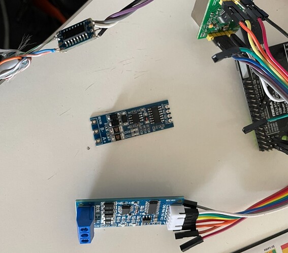
Regarding your video #3 I seen you have some boards that look very very similar to the RS485 boards I use to communicate with the SDM630 smart meter, with the same arduino I want to communicate with 2 or 3 devices, the first one is the smart meter, and it's done, now thanks to you MPP solar communication is also much done, and next I will add an bluetooth module to communicate with ANT BMS 180A-450A

Do you think those boards can also work for MPP SOLAR communication ? Both big boards in the photo bellow are RS485 to TTL.

I attached the Communication manual I received from MPP Solar when asking about the communication protocol of MPP SOLAR 8048MAX inverter
MAX Communication Protocol for HV7.2k LV5k V00 20200717.pdf (893.8 KB)

String QPI = "\x51\x50\x49\x61\x0D";
String QPIGS = "\x51\x50\x49\x47\x53\xB7\xA9\x0D";
String MUCHGC010 = "\x4D\x55\x43\x48\x47\x43\x30\x31\x30\xA6\xA2\x0D";

void setup() {
  Serial.begin(115200);
    Serial2.begin(2400);
      Serial2.setTimeout(20);

  // TEST SENDING COMMAND TO CHANGE PARAMETERS
  Serial.println ("Sending command MUCHGC010");
  Serial2.print(MUCHGC010);
  Serial.println ("Printign reply from inverter:");
  stringOne = Serial2.readString();
      Serial.println (stringOne);
        delay(2000);
          stringOne = "";     

  Serial.println ("Sending command MUCHGC010");
  Serial2.print(MUCHGC010);
  Serial.println ("Printign reply from inverter:");
  stringOne = Serial2.readString();
      Serial.println (stringOne);
        delay(2000);
          stringOne = "";           
  // END TEST SENDING COMMAND TO CHANGE PARAMETERS 

  // TEST SENDING COMMAND Device Protocol ID Inquiry
  Serial.println ("Sending command QPI");
  Serial2.print(QPI);
  Serial.println ("Printign reply from inverter:");
  stringOne = Serial2.readString();
      Serial.println (stringOne);
        delay(2000);
          stringOne = "";     
          
  Serial.println ("Sending command QPI");
  Serial2.print(QPI);
  Serial.println ("Printign reply from inverter:");
  stringOne = Serial2.readString();
      Serial.println (stringOne);
        delay(2000);
          stringOne = ""; 
  // END TEST SENDING COMMAND Device Protocol ID Inquiry        
}


void loop() {
  Serial.println ("Sending command QPIGS");
  Serial2.print(QPIGS);
  Serial.println ("Printign reply from inverter:");
    stringOne = Serial2.readString();
      Serial.println (stringOne);
        delay(2000);
          stringOne = "";
}

I tried now to add in void setup() two commands that will be send only once, one was to SET the Inverter AC charger to 10A (currently at 30A) and another one was to query communication protocol ID: QPI

For the first one command
MUCHGC010 = "\x4D\x55\x43\x48\x47\x43\x30\x31\x30\xA6\xA2\x0D";

I got no reply, in communication protocol manual it's this description:

3.4 MUCHGC: Setting utility max charging current
Computer: MUCHGC
Device: (ACK if device accepts this command, otherwise, responds
(NAK
Setting value can be gain by QMUCHGCR command.
nn is max charging current, m is parallel machine number.

For the second command:
String QPI = "\x50\x49\x82\x61\x0D";
//update .. I later found out the entire string was wrong, also CRC had one missing character
//the correct string is String QPI = "\x51\x50\x49\xBE\xAC\x0D";

I think the HEX conversion is wrong, I used this online tool and it shows me 51 50 49 for QPI.

I tried with your converted hexadecimal and I got (NAKss reply from the inverter, as it did not accept the command. I also tried with the modified String QPI = "\x51\x50\x49\x61\x0D"; but probably the CRC also needs to be modified, and I haven't understood yet how to modify it, I still haven't watched all your videos :slight_smile: but I will.

What I also noticed is that the first time the inverter receives QPIGS command, it replies with (NAKss, don't know why, but the next QPIGS commands, all have the correct reply from inverter.

Sending command MUCHGC010
Printign reply from inverter:

Sending command QPI
Printign reply from inverter:
(NAKss

Sending command QPIGS
Printign reply from inverter:
(NAKss

Sending command QPIGS
Printign reply from inverter:
(226.6 49.9 226.6 49.9 2627 2575 032 355 00.00 001 000 0031 02.
Sending command QPIGS
Printign reply from inverter:
(226.4 49.9 226.4 49.9 2671 2590 033 355 00.00 001 000 0031 02.

UPDATE. I watch the video #8 and I understood how to calculate the CRC, and I did for the QPI command, and now I finally have an response from the invertor when I inquiry the QPI command, but the same, the first QPI command has a NOK response, the second one has PI30, but the first command it still has no response from the invertor and I checked the HEX and CRC and it seems to be correct

Sending command MUCHGC010
Printing reply from inverter:

Sending command MUCHGC010
Printing reply from inverter:
(NAKss

Sending command QPI
Printing reply from inverter:
(NAKss

Sending command QPI
Printing reply from inverter:
(PI30š

Sending command QPIGS
Printing reply from inverter:
(PI30š

Sending command QPIGS
Printing reply from inverter:
(236.2 49.9 236.2 49.9 1016 0951 012 402 00.00 002 000 0031 02.
Sending command QPIGS
Printing reply from inverter:
(236.3 49.9 236.3 49.9 0992 0926 012 403 00.00 001 000 0031 02.
Sending command QPIGS
Printing reply from inverter:
(236.3 49.9 236.3 49.9 0992 0926 012 403 00.00 001 000 0031 02.
Sending command QPIGS
Printing reply from inverter:
(235.9 49.9 235.9 49.9 1013 0950 012 403 00.00 002 000 0031 02.
Sending command QPIGS
Printing reply from inverter:
(235.9 49.9 235.9 49.9 1013 0950 012 403 00.00 002 000 0031 02.

You are welcome

I have also got a meter that do RS485 communication, that is work to do. The 485 level shifters will help me in that but when that’s going to happen mostly depends upon Covid holidays :wink: . So far I have no experience of RS485 and very a limited of Bluetooth therefore, can’t assist on these. Though what I understand about RS485 is that if its HIGH is 12 then LOW is -12 whereas in RS232 High is 12 and Low is 0, so my guess is RS485 level shifters will not work on RS232.

I will recheck String HEX commands, may be I copied from wrong file , that’s why there are errors and edit earlier message accordingly.

The First NAK is may be due to exclusion of While command or not FLUSH ing the Buffer. Try using this command to clear buffer before printing to Serial 2

while (Serial.read() >= 0);

or this one

while (_tx_buffer->head != _tx_buffer->tail);

But First try to increase timeout to 1000, may be 20 milli seconds is too quick in your case


Serial2.setTimeout(1000);