I'm graphically limited, but the connections are simple to understand. I've described it here:
The module I'm using has an input called RTS, which is connected to both DE & !RE. Therefore, for the transmitter RTS=1 and for the receier RTS=0.
I'm graphically limited, but the connections are simple to understand. I've described it here:
The module I'm using has an input called RTS, which is connected to both DE & !RE. Therefore, for the transmitter RTS=1 and for the receier RTS=0.
Just to clarify, you have removed the 120R resistors from both of the Sparkfun boards?
Do you have a basic multimeter/voltmeter to hand?
I've never used any external resistors in this project. If there are internal ones within the Sparkfun boards - they're still there.
Yes, and also a logic analyzer (by Saleae). What do you recommend?
You lack pen and paper and a camera ?
RS-485 is a 5v protocol normally, maybe the board you have can run on 3.3v but for that i need a link to the exact board.
Fair enough.
Should be fine like that, but if you start to use more slaves, the extra terminators will have to go.
Well the obvious is to set one breakout board up as a driver, set the logic input 'HIGH' and measure the voltage between A & B, and then repeat this for a logic 'LOW'
It can receive 3-5V, I chose 3.3V so it would correspond to the arduino's GPIO.
Link: https://www.sparkfun.com/products/10124
Got it.
Ok, I'll try that in the coming days. What values should I expect to measure?
@dekel12121 Sorry for the delay in responding. I was going to follow up with what @Deva_Rishi said:
You should see a +ve voltage between A & B with the pin Sparkfun call RX-I in one logic state. When you change the logic state of the RX-I pin you should see a similar but -ve voltage.
The SP3485 datasheet suggests that the voltage should be in excess of +2V or -2V depending on the state of the data in pin.
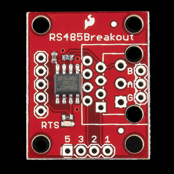
Just a quick sanity check - i'm looking at the Sparkfun website at the picture of the BOB-10124
And without load, Vcc - 0.4v according to the datasheet but there is a load because of the terminator.
Agreed, according to the schematic the numbers actually refer to the pins on the SP3405, so why to just use the Receive pin and the !RE & DE on 2 separate pins while they are connected on the PCB ? The same choice is copied on the RJ45 connector thoigh, so maybe it is some kind of standard pin configuration.
For sure !
And drive !RE & DE
So from top to bottom on that picture
About that, i just saw that the terminators are actually 220R which means that it will be a tad less sensitive,
nb 4 boards will take you to 55R which is just about the limit in the RS485 test circuit in the datasheet. (fig.1)
I am sorry but i disagree.
Please read here @paragrahp signals :
here @ paragraph 1:
Here @ paragrahp 7 :
Also here :
Specially in the last link Ti points out that there must be common wire.
Please note that i said common wire not common groud since common ground could create a ground loop.
For best performance and reliability galvanic isolation must be implemented.
Not quite. Over long distances only i would say or under heavily noisy environment
Just for testing purposes you should be fine. over long distance though you will experience data loss at irregular times. That is based on my experience.
That is correct
Yep 120Ohm is a better choice i think and good enough for cat5e cable impedance. Bus terminating resistors are calculated based on cable distance and impedance.
Ive been thinking.
I agree with that approach also. That's what i would have done also. After you communicate with the uarts set one transceiver as driver and the secons as receiver and send from your arduino on the driver side to the arduino on the receiver side. if you connect A to A and B to B it sould work.
Remember that depending on the baud rate you use, the signal transition time from high to low will probably bee too fast for a multimeter to capture and measure voltage. In these cases an oschilloscope is needed though most of us dont have one at home.
One easy way i can think of for testing the moduls is connecting the driver's inputs to vcc and gnd respectively and then measuring the output with the dmm. after reverse the vcc and gnd on the inputs and measure the output again. do i make sense ?
The basic idea there was to show that the line driver was working by applying a very slowly alternating logic level to DI and observing the voltage across A & B (a slightly modified blink example should suffice), rather than trying to observe the result of actual serial data transmissions.
You are free to agree with whatever you want.
Yeah you should change the pin number, or actually, just connect DI to pin 13. 1 second is perfect.
It is just to confirm that it has been connected properly.
definitely, but Sparkfun anticipated that 4 boards might be on the bus and with their value, that is not a huge problem. (their reasoning is though. Terminators do not belong everywhere, and are better off omitted then to many of them.)
Serial.begin(115200);
In my opinion you should be able to cover several 100 meters at that speed.
Regardless of RTS pin value?
That is how my boards are connected.
I'll try that too, thanks.
Great, I like it simple.
I will probably use a delay to lower the rate of change.
If nothing will be connected to TX-O I would expect to measure 0V?
I used 9600. Maybe the change will come from this simple definition.
Sorry, I missed that bit out - RTS should be tied HIGH to enable the line driver.
In case it helps, I have a MAX3485 breakout board here. It has a 120R across A & B, and it has a 4K7 pulldown from B to GND, and a 4K7 pullup from A to 3.3V.
I have a DMM with the +ve lead connected to A and the -ve lead connected to B
When powered from 3.3V, and the line driver enabled, connecting DI (Sparkfun call this RX-I and it's the second pin down on the 5-pin conn on the left in the picture in post #26) to GND the DMM shows -1.38V and if I then connect DI to 3.3V, the DMM shows 1.41V.
That shows that the line driver is working in TX mode.
When I disable the line driver (i.e. GND onto RTS) and connect the DMM between GND and RO (what Sparkfun calls TX-O), and connect A & B as follows:
B to GND & A to 3.3V - DMM reads 3.29V
B to 3.3V & A to GND - DMM reads 0V
That shows that the line driver is working in RX mode.
If you see similar results with your Sparkfun boards, then at least we know they are working.
Hope some of that helps you out.
Following this experiment, I get results with the values of +-2.5V, exactly in the cases that you've described.
Ditto, I read 3.26V.
So my Sparkfun boards are working as expected.
Why don't I see the incoming data on the serial monitor?
Good news about both boards.
The next step I would take is to connect the 2 boards together using the A, B and GND signals. I'd then set one with RTS high and the other RTS low. I'd then see if I could send a simple 1 and 0 over the RS485 link by connecting the pin on the TX side to either 3.3V or GND.
That should simply check your RS485 link is working.
EDIT: Should have said to check the output on the RX side with the DMM.
That soulds like an idea. Or dont use any of the arduino pins at all. Just connect the A and B lines to respectively VCC and GND (differentially) And watch the output going from high to low and from low to high after reversing vcc and gnd.
Exactly. The suggested next step was to build on what was already proved with the hardware.
Assuming that the RS485 link worked in isolation from any Arduino, my next suggestion (and I think it was mentioned in an earlier post) would be to directly connect the 2 Arduinos together - i.e no RS485 hardware used. That would test the serial link between the 2 boards.
If that was successful, then introduce the RS485 hardware and test again.