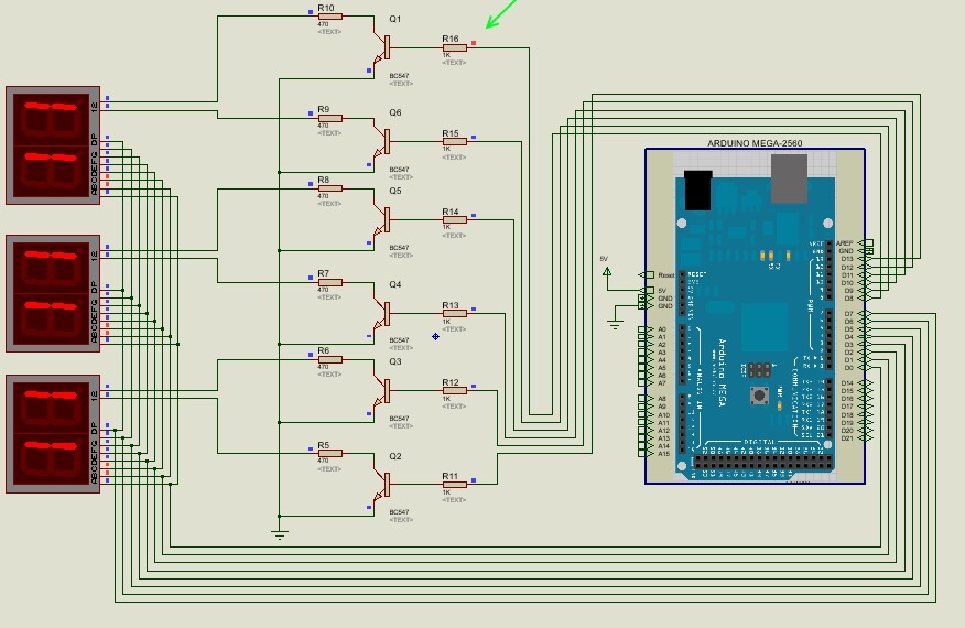
I am using NPN transistors to select which of the common cathode digits should show the output of the 8 data I/O ports (7 segments + dot).
The problem is that even though the base of only one transistor gets turned on, all the digits show the output of the 8 I/O ports (7 segments information). Heck even if I disconnect the base of all transistors, all the digits still show the data.
I even simulated the circuit using Proteus and the simulation exhibits the same problem.
In the photo the output digit is "1" and it is supposed to be shown on the first digit only. Therefore two data lines get turned on + the line which determines the digit (i.e. connected to the base of the first transistor).
Could someone tell me why all transistors are conducting electricity (enough to turn on all of the digits)?
I suspect you've wired the transistors incorrectly. The basic circuit is correct, although drawn all upside-down
and back-to-front which is confusing. Or perhaps you have coding problem?
This is a horrible design. The digit drivers set the current, so the same current is used for one segment as for eight. So a "-" symbol will be driven 8 times as hard as a "8.". It's laughable that anyone would do that. It only takes two more resistors (putting them on the segment lines instead of the digit lines) to fix that. What a crock.
The whole point is that only one digit should be shown at any moment (impossible to use otherwise unless you want to show a number on all of them) and the digits are scanned repeatedly. So it is not laughable as you say.
In the current buggy status, all of the digits turn on and the load on the eight segment driver lines is higher than acceptable, but if it functions properly and you drive one digit at a time, it will be fine.
@MarkT
I changed the transistors to reduce the confusion. As shown in the simulation snapshot, only one of the transistors has a voltage on its base (so programming is fine) and the segments selectors are also fine (digit '1' has caused two of the segment lines to turn on).
No, in fact that circuit is total rubbish. Did you not read the correction posted on the page you cite?
So given that you have corrected the circuit to the first one in the article, not the second, is it working now or not?
If it is not, then you need to post your code according to the forum instructions for posting. That is, the code you are actually using, not what is on that other website - because we would have every reason to suspect that it is not the same. And although I can read the stupidly coloured (black on grey) code on the page with some difficulty, I have no intention to waste my time guessing whether yours is the same. And I doubt anyone here will say otherwise.
Oh, and when you have finished mucking about with this circuit purely for amusement, if you really want to use these displays for anything serious, do it properly and get a MAX7219. The ones cheaply available on eBay, complete with a mounting board and a LED matrix (which you can simply ignore), are generally quite reliable.