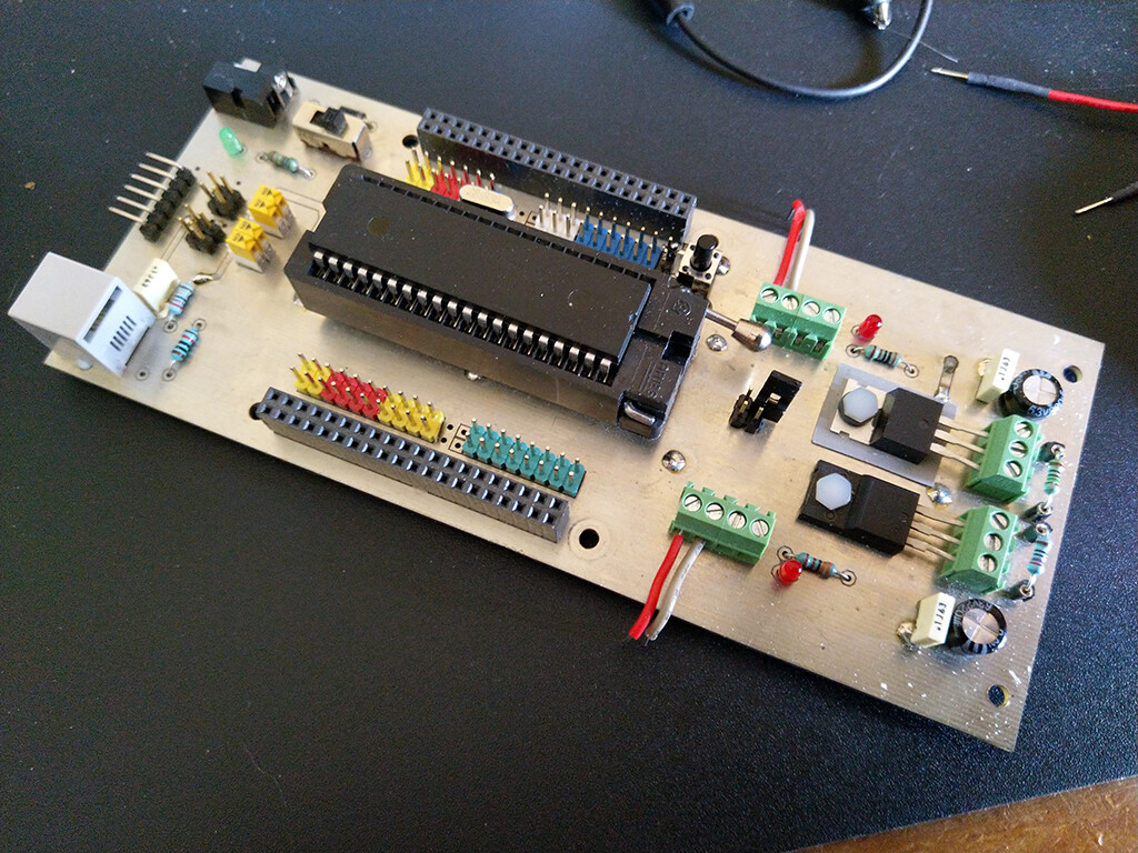
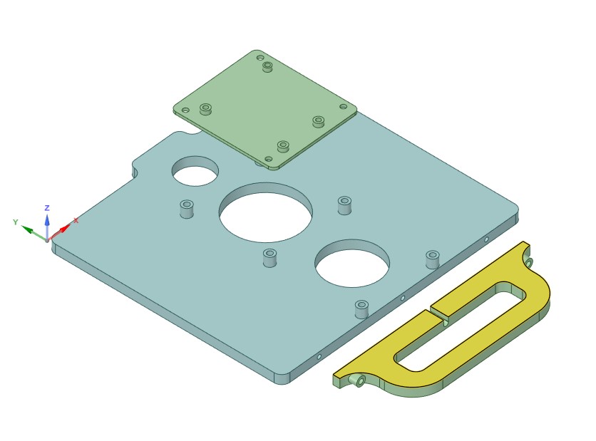
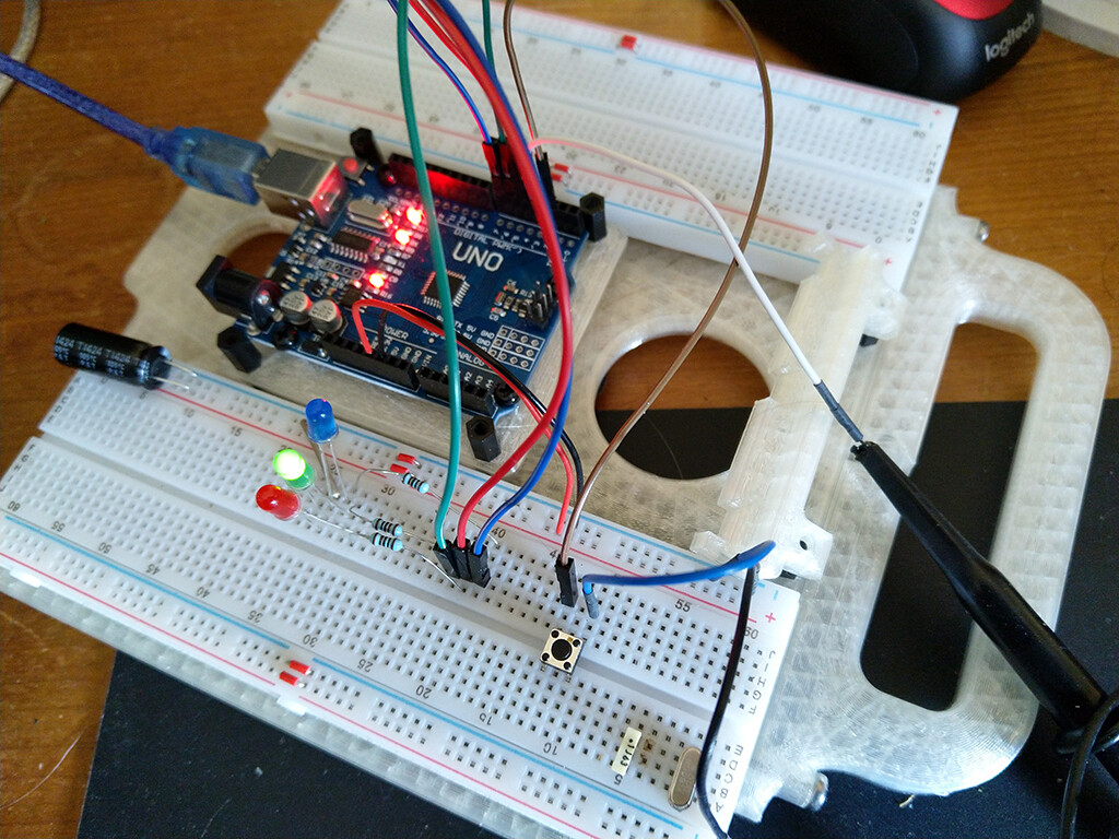
Originally I had this with a homemade pcb which carried a PIC 18F452 which I could program through ICSP. Then I discovered the joy of Arduino and made an adapter plate for my UNO so I could use that instead
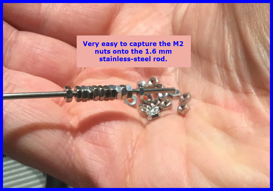
In my latest project, I had to install quite a few small nuts onto small screws.
With large fingers, no figure nails, and ‘Arthur’ in my joints, frustration soon set in.
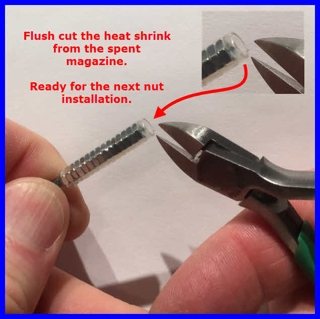
The solution was to come up with the following method to make nut installation simple and easy.
You need:
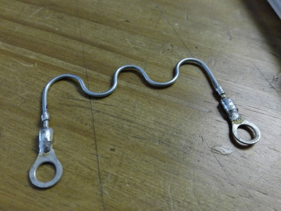
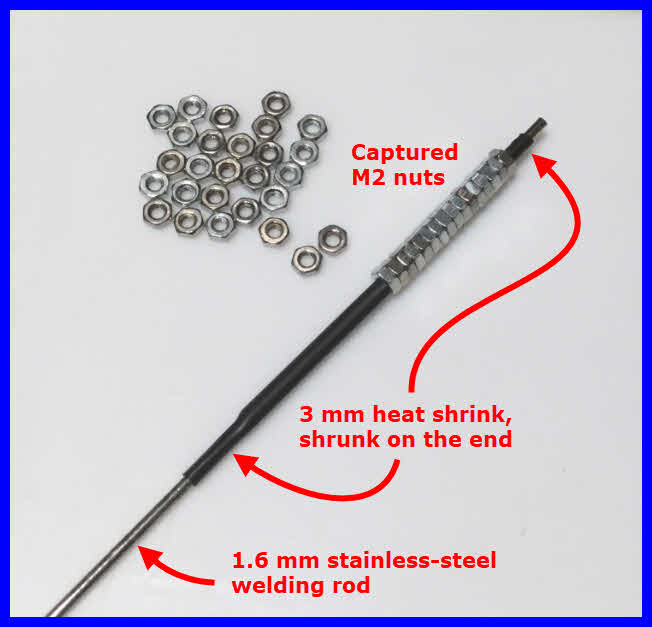
1.6 mm stainless steel welding rod. To assemble a series of M2 nuts.
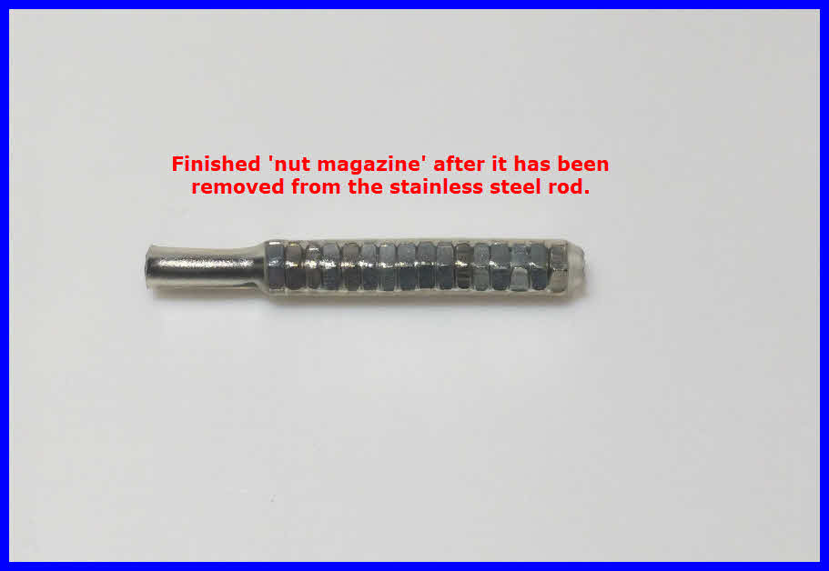
6 mm heat shrink 4:1, glue lined. Used for the ‘nut magazine’.
3 mm heat shrink regular 2:1. To keep the nuts from falling off the stainless-steel rod and to
prevent any 6 mm heat-shrink glue from sticking to the rod.
For the purpose of this discussion, clear heat shrink was used to make things easy to see.
However, using 4:1 heat shrink, glue lined, is recommended.
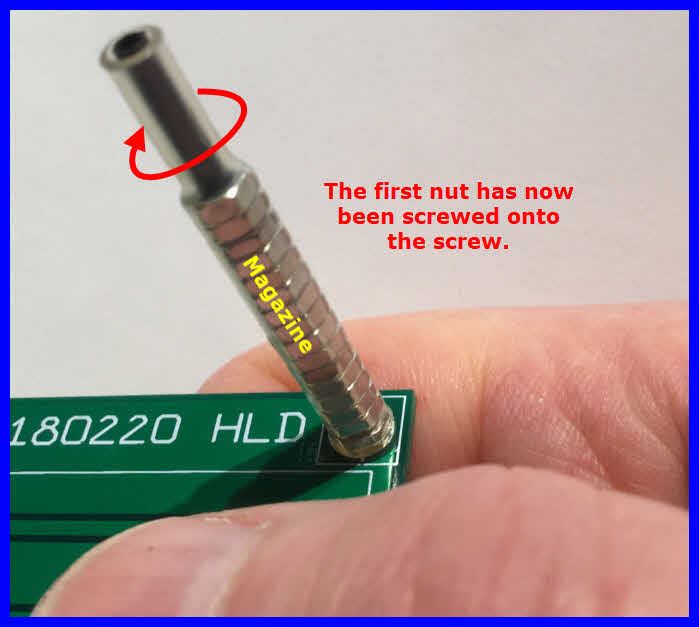
Make up several nut magazines ahead of time so they are ready when they are needed.
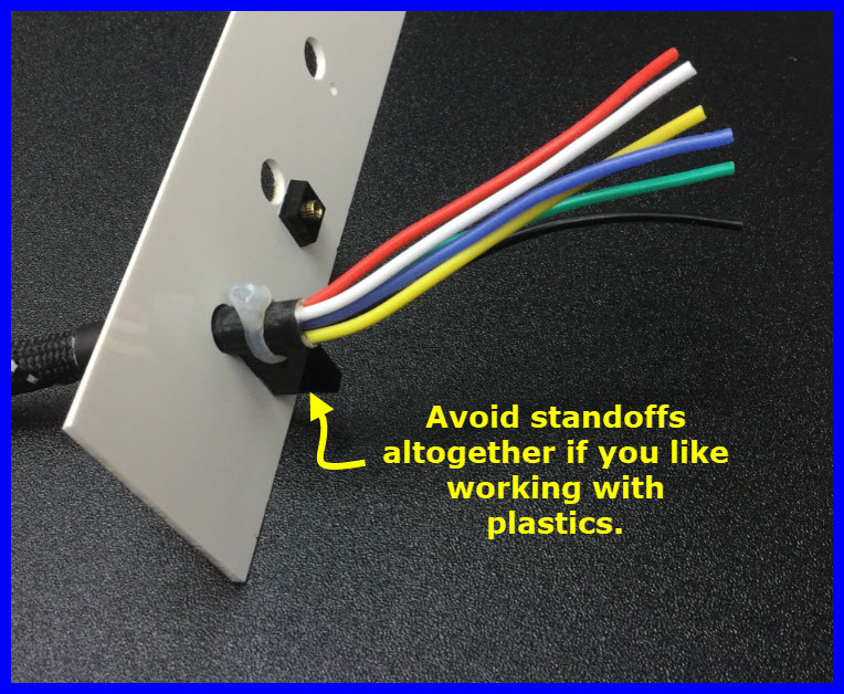
This method can be used with other similar components like small stand-offs, washers etc.
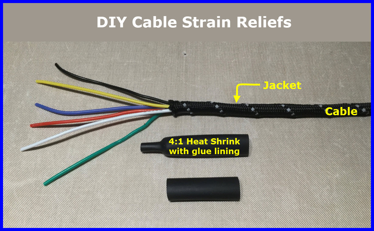
We first need to add 4:1 heat shrink to our cable.
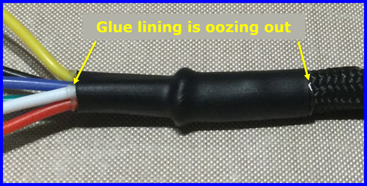
When we shrink the heat shrink, we see the jacketed portion has a larger diameter than the stripped portion.
If this difference in diameter needs to be increased, add a short piece of heat shrink under the outer heat shrink.
For the left side of the heat shrink shown, 1/2 inch over the stripped wires should be adequate.
It is this portion that will be tied to a standoff.
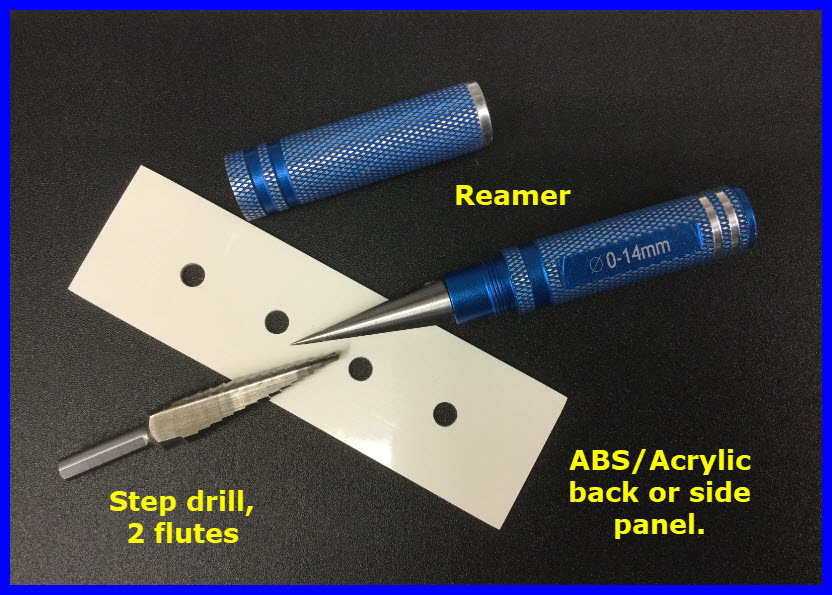
Use a step drill to make a hole in the chassis back or side.
The cable hole fit should be tight; use a reamer or file to tune the diameter.
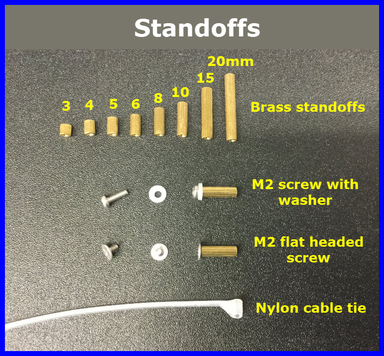
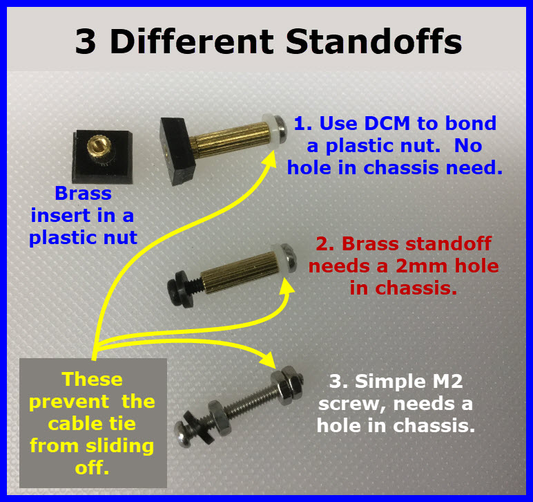
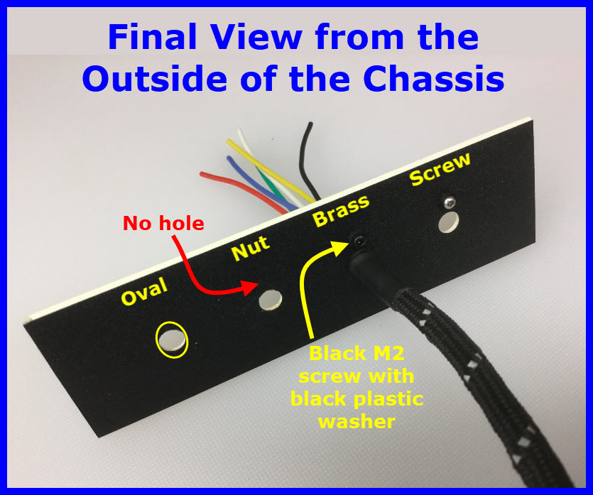
Four methods are shown for tying the cable.
Each method prevents our cable from turning or being removed from the hole in the chassis.
I prefer the ‘Brass standoff’ or ‘Brass standoff plastic nut’ method.
If you use an oval hole, you will have to form the cable end into shape with pliers.
Make sure you get a good fit and the cable does not turn in the oval hole.
You still need a cable tie to prevent the cable from pulling out of the chassis.
The oval method does not need a standoff, however, the strain relief it offers is not very good.
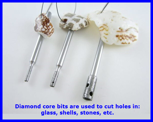
While doing some lapidary work, it became obvious the bits I was using could be repurposed into the electronics area.
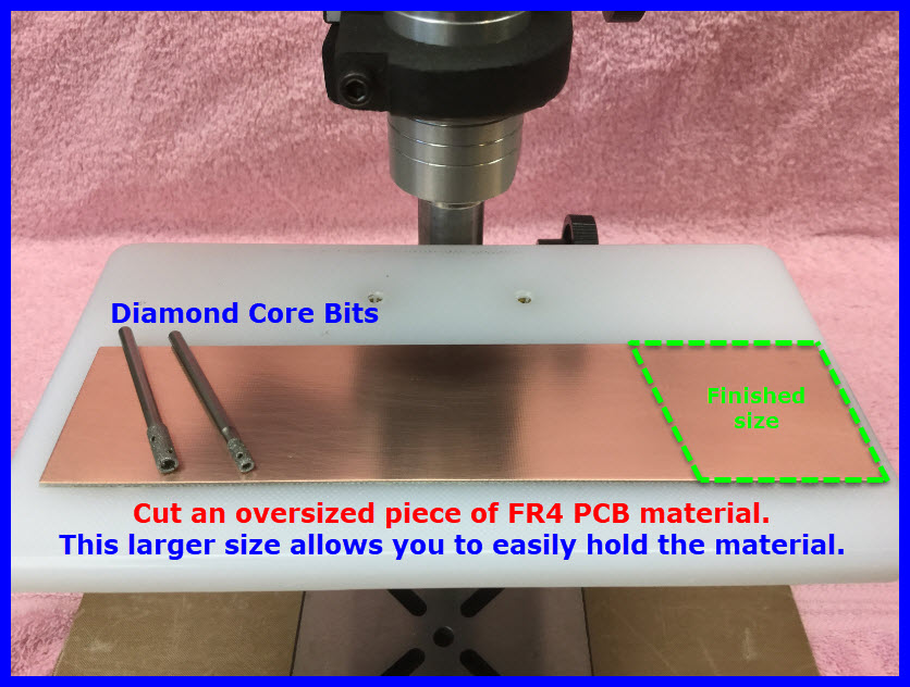
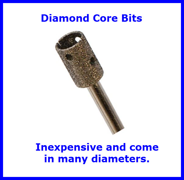
Wet/dry ‘Diamond Core Bits’ are used in making jewelry and in cutting holes in glass; for example making a hole in a bottle for a power cord to go through. These bits come in many diameters and are relatively inexpensive.
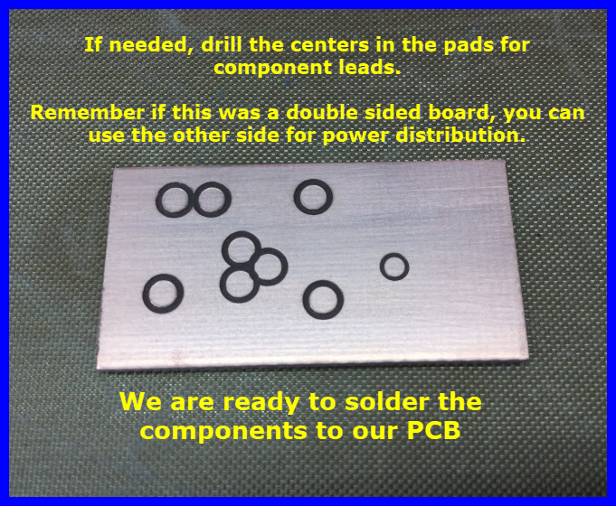
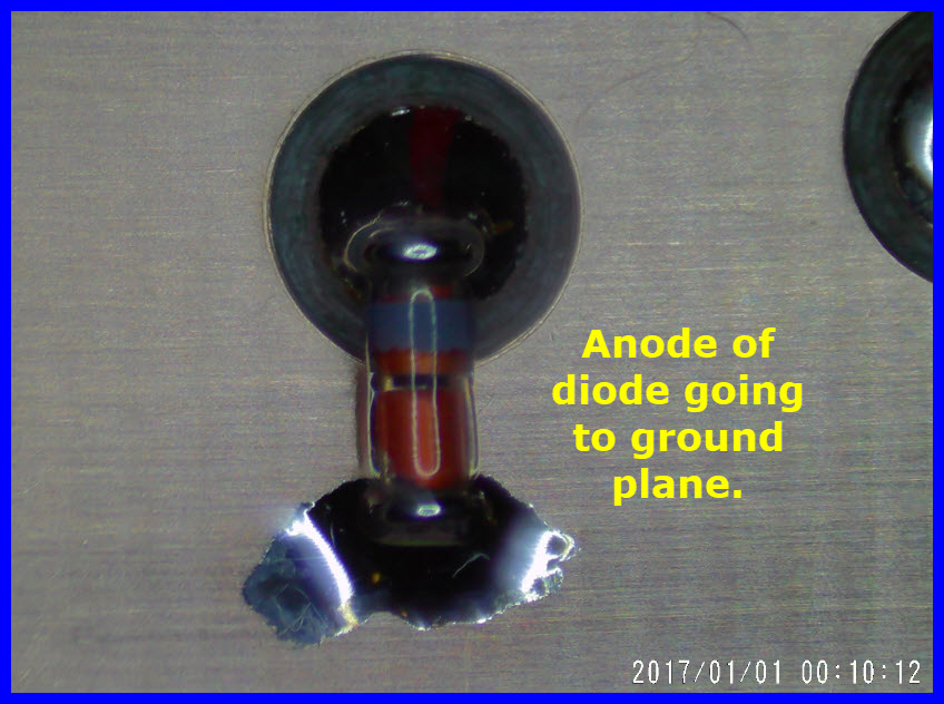
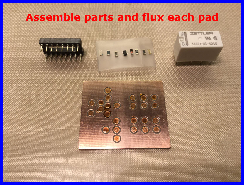
Core bits are hollow and nicely make solder pad shapes in PCB FR4 material.
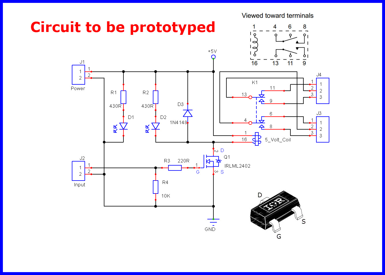
The following discussion shows how these bits can be used to manufacture a point to point wiring circuit board. The process is easy and produces a very nice finished product.
Equipment:
Diamond core bits, I use mostly .110” and .070” inside diameter.
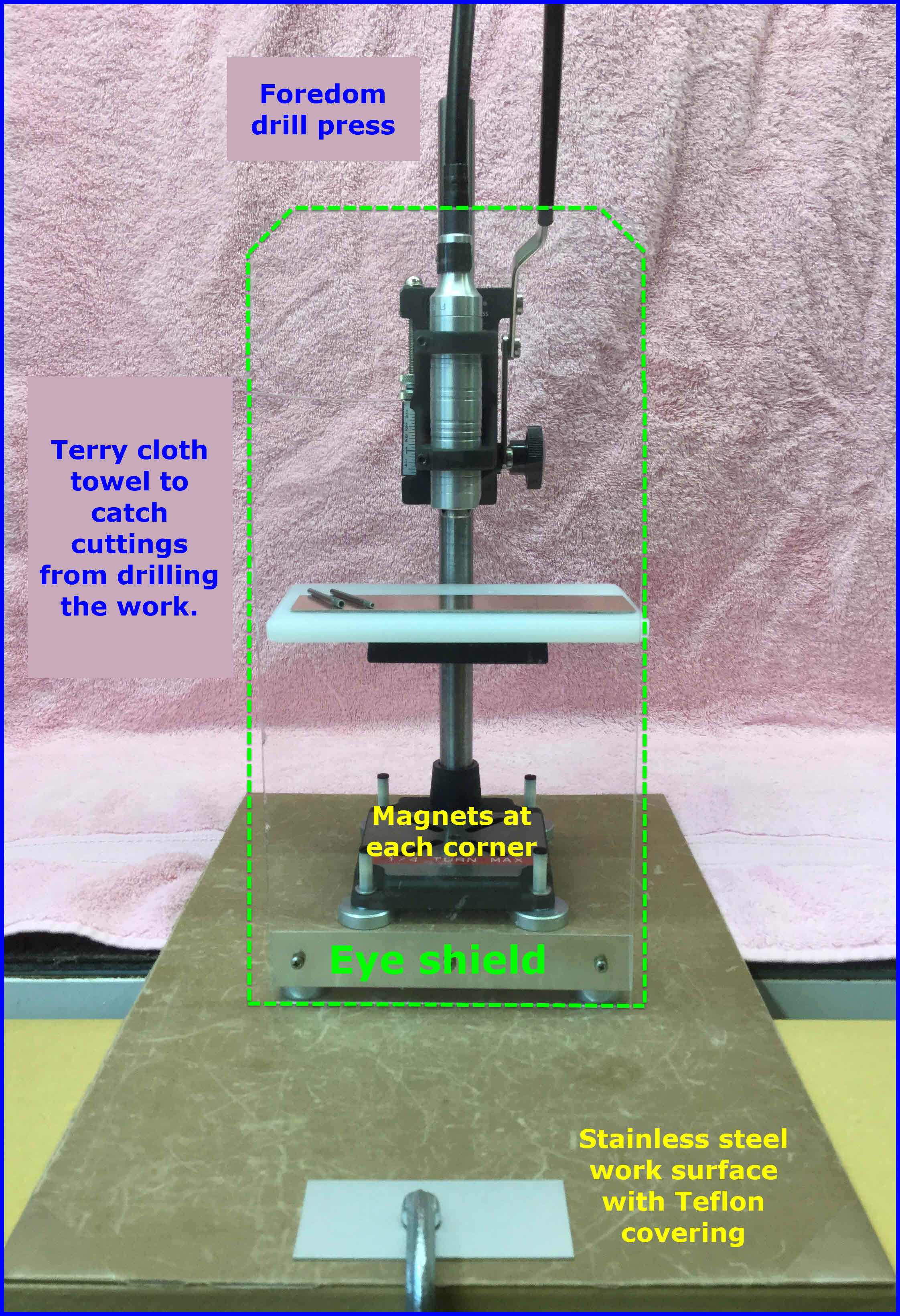
Foredom/Dremel drill press.
Other tools and parts as see in the following images.
A drill press is highly recommended for this process as you have full control over positioning and drill depth.
Since a core bit has diamonds in its surface, the bit last a very long time.
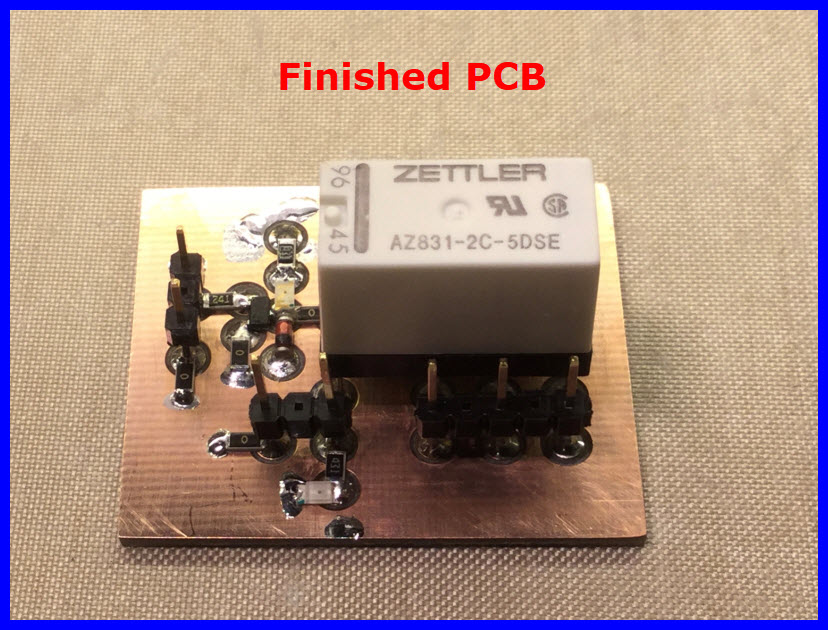
Using a .070" core bit, you can easily place pads at .1" centers (you may have to wear a head/eye magnifier).
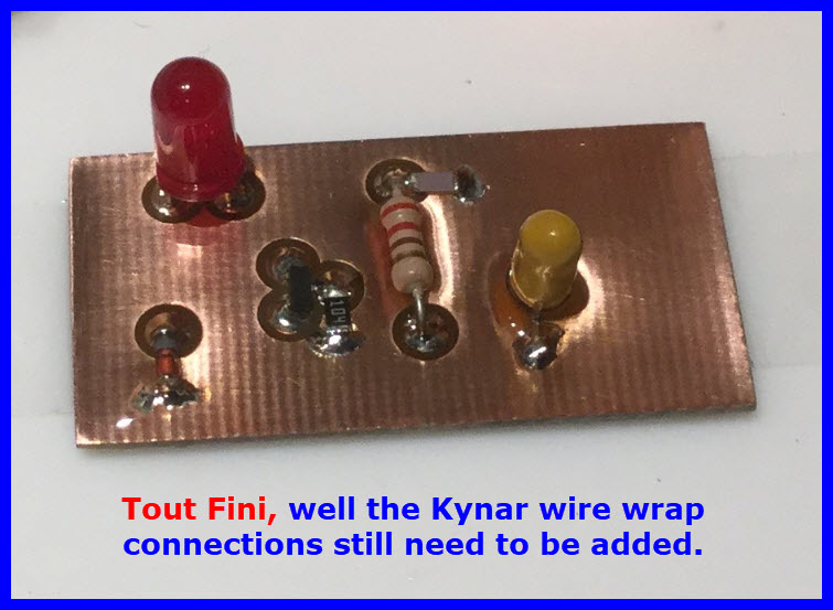
Not shown in the images is the pad interconnections using 30AWG Kynar wire wrap wire.