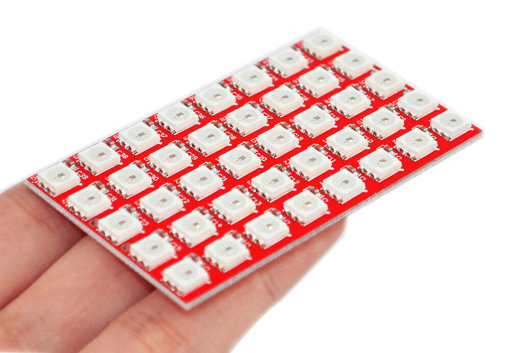
I've been working on a 5*5 RGB led matrix project. It uses shift registers to control the anodes of the common cathode leds. It's been displaying the right patterns for a while, but recently it suddenly stopped working. I've tested the connections with a multimeter, but I still can't find the issue. It displays the right pattern once in a while, but most of the time it displays random colors on random pixels. This is the code:
/*
  ShiftRegister74HC595 - Library for simplified control of 74HC595 shift registers.
  Created by Timo Denk (www.timodenk.com), Nov 2014.
  Additional information is available at http://shiftregister.simsso.de/
  Released into the public domain.
*/

#include <ShiftRegister74HC595.h>

// create a global shift register object
// parameters: (number of shift registers, data pin, clock pin, latch pin)
ShiftRegister74HC595 sr (3, 8, 10, 9);

//latch = 9,
//ShiftRegister74HC595 sr (3, 10, 8, 9);

const int cathodes[] = {2,3,4,5,6};


//const int reds[] = {1,0,7,14,13};
//const int greens[] = {15,22,21,20,19};
//const int blues[] = {12,11,10,9,8};

const int reds[] = {6,7,0,9,10};
const int greens[] = {8,17,18,19,20};
const int blues[] = {11,12,13,14,15};

boolean matrix_red_Values [] {
  1, 1, 1, 1, 1,
  1, 0, 0, 0, 1,
  1, 0, 1, 0, 1,
  1, 0, 0, 0, 1,
  1, 1, 1, 1, 1
};
boolean matrix_green_Values [] {
  0, 1, 1, 1, 1,
  1, 1, 1, 1, 1,
  1, 1, 1, 1, 1,
  0, 1, 1, 1, 1,
  0, 1, 1, 1, 1
};
boolean matrix_blue_Values [] {
  1, 1, 1, 1, 1,
  1, 1, 1, 1, 1,
  1, 1, 0, 1, 1,
  1, 1, 1, 1, 1,
  1, 1, 1, 1, 1
};

void setup() {
  Serial.begin(9600);
  for(int x=0; x<5; x++)
    pinMode(cathodes[x], OUTPUT);

}

void loop() {


 for(int cathodeCycle = 0; cathodeCycle < 5; cathodeCycle++){
   digitalWrite(cathodes[cathodeCycle], LOW);
   digitalWrite(cathodes[cathodeCycle-1], HIGH);

   for(int x = 0; x < 5; x++){
      sr.set(reds[x], matrix_red_Values[(cathodeCycle * 5)+ x] );
      //delay(1);
    //  for(int y = 0; y < 5; y++)
   //    sr.set(reds[y], LOW);

      sr.set(greens[x], matrix_green_Values[(cathodeCycle * 5)+ x] );
      //delay(1);
    //  for(int y = 0; y < 5; y++)
    //    sr.set(greens[y], LOW);

      sr.set(blues[x], matrix_blue_Values[(cathodeCycle * 5)+ x] );
     // delay(1);
    //  for(int y = 0; y < 5; y++)
    //    sr.set(blues[y], LOW);

    // delay(100);
     sr.setAllLow();
     //Serial.println(millis());

   }
   //delay(100);
    // sr.setAllLow();
 }
 digitalWrite(cathodes[4], HIGH);


}
The schematic is attached
led matrix.pdf (28.6 KB)

