
Yes, see my explanation in #9 above. The relay Vcc must connect to the 5 V at the WeMOS, not the 3.3 V.
I see I forgot to post a link to the completed project! Pictures of the wiring and stuff can be seen at:
and the signal it drives...
DaleSchultz:
I see I forgot to post a link to the completed project! Pictures of the wiring and stuff can be seen at:Cabin Layout: Outdoor signal with wi-fi control
and the signal it drives...
Thanks but it doesn't show the connections clearly. Should I connect the VCC from the relay to the 5V pin on the D1mini (where the 5V from the DC plug is already connected?)
the answer is YES connect it to the 5V pin. See answer #9 above.
Hey I am a begnner..!!! And I have the same issue.. Please help my esp8266 wifi module don't have 5v.. So I don't know how to do the 5volt part..
Hey! I am beginner and I have the same problem.. There is no 5volt in my esp8266 so I don;t know how to do this 5volt part.. Kindly Help I am stuck in this since last week... I have tried all the things but can't get the solution... Here is my esp8266 wifi module..
Thanks in advance!!!
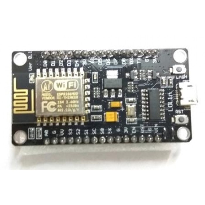
That appears to be a NodeMCU. How are you providing power to it? Are you feeding 5 V to it by the micro USB jack? If so, your (almost) 5 V is appearing on the "Vin" pin, so you connect your relay "VCC" to it.
If you are not feeding 5 V to it from a "phone charger" or similar by the micro USB jack, how on earth are you powering it?
DaleSchultz:
I see I forgot to post a link to the completed project! Pictures of the wiring and stuff can be seen at:Cabin Layout: Outdoor signal with wi-fi control
and the signal it drives...
Hi, i still see in this document that you are connecting VCC from the arduino to the relay despite powering the JD-VCC pin from the dedicated 5V line. Your picture shows you are powering VCC and JD-VCC from the same source. Since you are powering both these pins separately from the same line, can you just reattach the jumper and save a connection?
mcconkeyagar:
Since you are powering both these pins separately from the same line, can you just reattach the jumper and save a connection?
You can if you want the transients from relay actuation to be propagated into the ESP8266 and cause crashes.
This problem is the reason so many people end up using separate supplies for the Arduino/ ESP and the relay board. If you are using a 5 V relay module from the same power supply, then the 5 V and ground power wires to that relay module run directly (and together as a pair) from the output terminals of the power supply - the point at which the output bypass capacitor is placed - while the 5 V and ground to the Arduino also separately run together as a pair from those output terminals of the power supply.
This separates any current surges/ dips that the relay board generates, from the Arduino supply. (There really should be a 1 mF capacitor across 5 V and ground at the relay board itself in any case.)
If the relay board has separate "Vcc" and "JD-VCC" terminals, the "JD-VCC" runs to the power supply, while the "VCC" runs together with the "IN" connections back to "5V" on the Arduino.
1 Like