Am I required to disable those internal pull ups or just ignore them ?
I looked for a bit for this particular question but I did not find any answers.
No you don't need to do anything.
Just communicate with the battery like it was a normal I2C device.
I did as advised using only 10k ohm external pull ups and I run the script:
#include <Wire.h>
#include <Arduino.h>

#define Batt_Address 0x0b //0x0B Smart Battery address

#define temperature_register 0x08 //0x08 cell-pack's internal temperature (°K)

void setup() {

Serial.begin(115200);

Wire.begin();

}

void loop() {

//Get RSOC

Wire.beginTransmission(Batt_Address); //Send a Request

Wire.write(temperature_register); //Ask for temperature

Wire.endTransmission(); //Complete transmission

Wire.requestFrom(Batt_Address, 2); //Request 2 bytes

byte MSB = Wire.read(); //Read MSB first

byte LSB = Wire.read(); //Read LSB

u_int16_t temperature = ((MSB << 8) | LSB) ; //Assign word to temperature

Serial.print("temperature: ");

Serial.println((double)temperature * 0.1); //convert to double and print to the serial monitor

delay(5000);

}
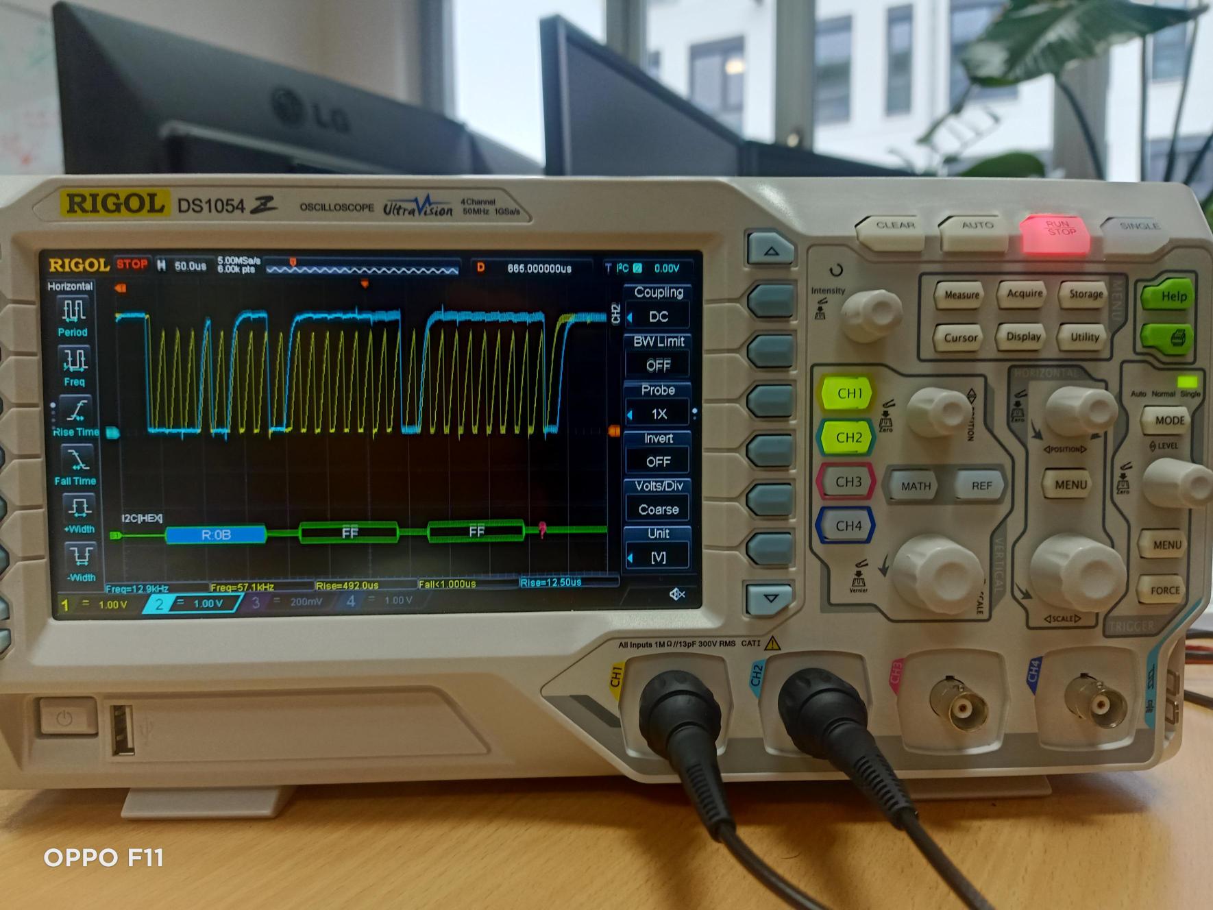
I wanted to read the temperature of the cells' pack but stilll I am getting "temperature: 6553.50" in teh serial monitor.
I hooked the SDA and SCL line to ch1 and ch2 respectively on the oscilloscope.
could you help me analyse this data please ?
I used the same horizental line as 0 for both channels.

If any important information is missing please ask me.
The trigger is set to ch1 (SDA).
Both the clock and data should be fairly square looking that go from 0V to 3.3V
So your clock does not look good
What does it look like on the oscilloscope if you remove all pull ups ?
Also not all bateries have to support all the fonctions.
Try requesting the battery mode 0x03
I tried different pull ups but still like @jim-p said my clock does not seem right at all.
Theses picture are taken with 4.7k Ohm resistors:


The first picture is for the overall and the other two are just zoomed halves.
These pictures show without resistors:


The first picture is for the overall and the other two are just zoomed halves.
for some reason the last bit was not acknowledge and also the rise time for both lines is too high.
As you can see in the top right corner of the images there is "I2C" which is an option in the osci for I2C communication.
How long are the wires between the ESP and the battery?
Did you try 0x03 instead of 0x08?
I am using normal wires of length a little bit less than 12cm each,
I just tried with the suggested register to get the BatteryMode (honestly I am pretty sure that the battery should and is expected to support all the mandatory functions in the Smart Battery Data Specification)
This is the script that I just run for the BatteryMode register:
#include <Wire.h>
#include <Arduino.h>

#define Batt_Address 0x0b //0x0B Smart Battery address

#define BatteryMode 0x03  //0x03 BatteryMode register

void setup() {
Serial.begin(115200);
Wire.begin();
}

void loop() {

//Get RSOC
Wire.beginTransmission(Batt_Address);  //Send a Request
Wire.write(BatteryMode);  //Ask for BatteryMode register
Wire.endTransmission();  //Complete transmission
Wire.requestFrom(Batt_Address, 2);  //Request 2 bytes
byte MSB = Wire.read(); //Read MSB first
byte LSB = Wire.read(); //Read LSB
u_int16_t BatteryModeRegister = ((MSB << 8) | LSB) ; //Assign word to BatteryModeRegister
Serial.print("BatteryModeRegister: ");
Serial.println(BatteryModeRegister, HEX); //print BatteryModeRegister to the serial monitor
delay(5000);
}
but still I get "BatteryModeRegister: FFFF" in the serial monitor, this is without any resistors.
I noticed that when reducing the resistance the rise time is reducing too that is why I went for 4.7k ohm resistance and now I will try smaller values.
If you have any more suggestions please let me know.
Thank you again for your guidance and patience.
A true SMB device will not be able to pull the bus low with low value pullups.
The fact that the clock looks better with a lower value pullup indicates that the bus is heavly loaded with capacitance but it should not be.
It should be fine with a 10K so I suspect there is something else wrong somewhere or those batteries are NOT SMB compliant.
PA-LEP1014.R001 this is the reference of the smart battery, it is from fey.

I just took this screenshot from fey's website and it mentiones that it is SMB compliant.
This is honestly confusing me as I am not able to identify what is the problem here to be able to fix it, I am just gessing and trying different things but the result is the same, the battery acknowledges its address but the last acknowledge is not true for some reason.
I also did not pay much attention to the capacitance because there is not much components in the circuit, it is just a board and a smart battery.
Just to make sure, the yellow line is for the clock and the blue line is for the data.
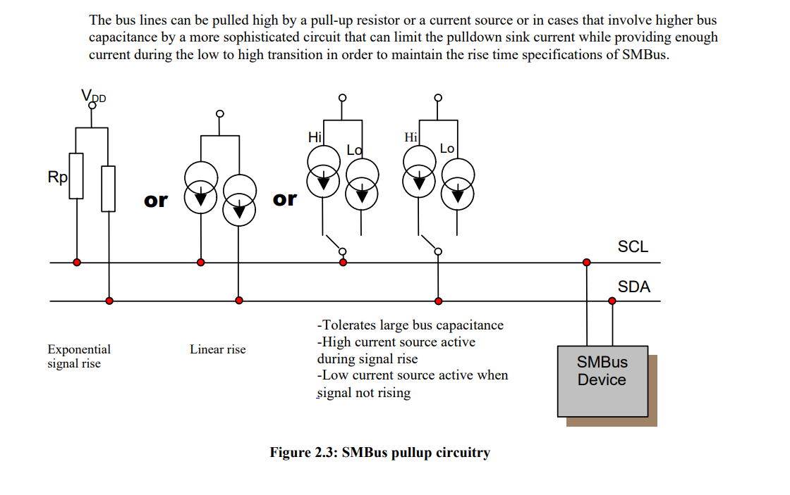
without resistors we can see a triangular clock but when I put resistors it becomes exponential which is the expected result because I am using resistors and not current source.
But the problem is with the rse time, it is too high for smbus communication.
But I cannot say for sure whether this is the main or only problem or not.
If you don't get the ACK then it means the battery has a problem. Try reading the BatteryStatus 0x16 it might tell you what is wrong.
I just tried this code (I made some modifications based on this post that I fond and it's said that it's working Using I2C for SMBus device communications - Libraries - Particle) to request the BatteryStatus as advised but still I see BatteryStatusRegister: FFFF in the serial monitor.
#include <Wire.h>
#include <Arduino.h>

#define Batt_Address 0x0b //0x0B Smart Battery address

#define BatteryStatus 0x16  //0x03 BatteryStatus register

void setup() {
Serial.begin(115200);
Wire.begin();
}

void loop() {

//read BatteryStatus register
Wire.beginTransmission(Batt_Address);  //Send a Request
Wire.write(BatteryStatus);  //Ask for BatteryStatus register
Wire.endTransmission();  //Complete transmission
Wire.requestFrom(uint8_t(Batt_Address), (size_t)2, true);  //Request 2 bytes
byte MSB = Wire.read(); //Read MSB first
byte LSB = Wire.read(); //Read LSB
Wire.endTransmission();
u_int16_t BatteryStatusRegister = ((MSB << 8) | LSB) ; //Assign word to BatteryStatusRegister
Serial.print("BatteryStatusRegister: ");
Serial.println(BatteryStatusRegister, HEX); //print BatteryStatusRegister to the serial monitor
delay(5000);
}
I tried with 10k Ohm and without but still the same result.
Could it be that I would need a BMS (Battery management system) in order to safely communicate with the battery because it has 4 cells packed togather ? I think that it is highly unlikely that this is the problem that I am facing but could this be a potential solution or is it irrelevant to the problems that I am facing ?
I used a PIC24 microcontroller to talk to the smart batteries I had. So the PIC was the Smart Battery System Manager (SBSM). It had 10K pullups to 3.3V. I had no problems.
It's been 10 years since I did the project but one thing I do remember is that the batteries would sometimes stop responding and the only way to get them working again was to discharge them and then recharge, then they would work
As seen here https://forum.arduino.cc/t/esp32-dev-reading-a-register-of-an-i2c-device/899399
You could try this
Wire.begin();
Wire.setClock( 50000L);
Hi ZX80,
thank you for your suggestion, I will check the forum you mentioned and try your suggestion.
I run the script below with and without "Wire.setClock( 50000L);" but in both cases I added the argument "false" to "Wire.endTransmission" and apparently that helped.
#include <Wire.h>
#include <Arduino.h>

#define Batt_Address 0x0b //0x0B Smart Battery address

#define BatteryStatus 0x16  //0x03 BatteryStatus register

void setup() {
Serial.begin(115200);
Wire.begin();
Wire.setClock(50000L);
}

void loop() {

//read BatteryStatus register
Wire.beginTransmission(Batt_Address);  //Send a Request
Wire.write(BatteryStatus);  //Ask for BatteryStatus register
Wire.endTransmission(false);  //Complete transmission
Wire.requestFrom(Batt_Address,2);  //Request 2 bytes
byte MSB = Wire.read(); //Read MSB first
byte LSB = Wire.read(); //Read LSB
u_int16_t BatteryStatusRegister = ((MSB << 8) | LSB) ; //Assign word to BatteryStatusRegister
Serial.print("BatteryStatusRegister: ");
Serial.println(BatteryStatusRegister, HEX); //print BatteryStatusRegister to the serial monitor
delay(5000);
}
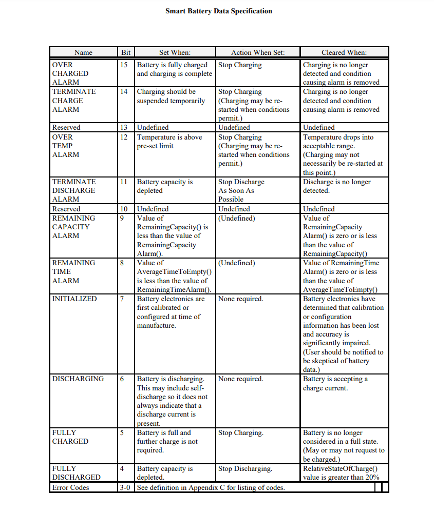
Now I get "BatteryStatusRegister: 1000" in the serial monitor rather than FFFF like before, but the result does not exactly make sense because, as you can see in the screenshots below, that bit is for "OVER TEMP ALARM" which is not supposed to be set because the battery is not working or in a very hot place for that alarm to be set.

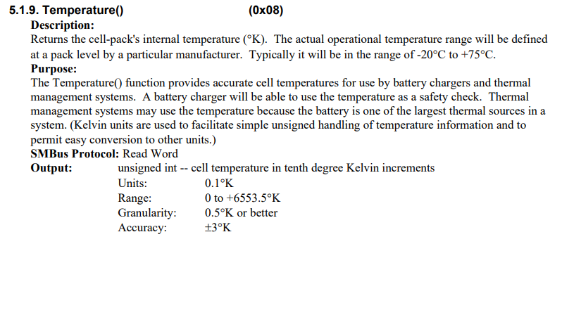
I will try to get "SpecificationInfo()" register and also "temperature" and see what results to have.
I tried the same script but for different registers,
for SpecificationInfo register I got FFFF for some reason which does not make sense. The it mapping is as shown in the picture below:

But for other registers like the temperature I am getting values around 30000 which gives around 30°C after conversion.
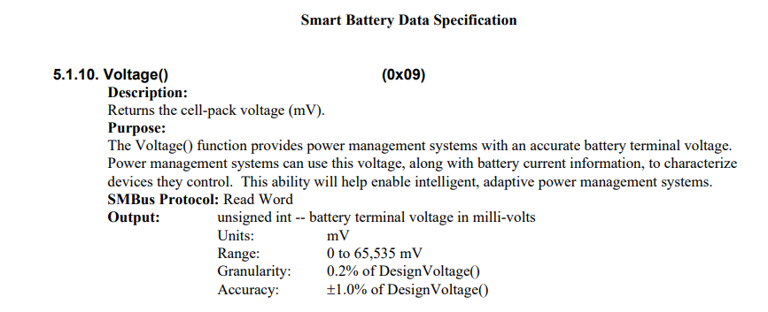
as to when reading the Voltage() register I get values ranging from 7700 to 8500 mV which does not correspond to the value I am reading at the terminal of the smart battery using a voltmeter
I am suspecting that this might be caused due to the non linearity issue specified in the below link but I am still investigating this:
Thank you all for sticking up with me this far, I really appreciate it.