<SOLVED>Re: Fast data logging using FRAM

it won't compile because some vital declarations are missing. TWBR, TWCR etc need to be declared presumably in some library or other.
It's not the I2C spec that will be helpful, but perhaps the I2C section of the ESP32 datasheet.

You can forget about the example you found, because things like TWCR are I2C peripheral control registers of the AVR processor that don't exist on ESP32. To implement the equivalent logic on your ESP board, you would have to completely replace the low-level code with substantially different (and more complex) code.

That library seems to send one byte at a time

However, I don't really see any reason that the Adafruit library should be especially slow, once you i2cSetClock() the frequency up to 1mbps. It SHOULD support the multibyte sequences if you use the multi-byte forms of write(). (Time to see the actual code you're using. Hint, hint.)

I think I may have found what I am looking for in:
ArduinoData\packages\arduino\hardware\avr\1.8.5\libraries\Wire\src\utility\twi.h

See the "avr" in that line? For ESP32 you need to look in the ESP32 directories like .../packages/esp32/hardware/esp32/2.0.2/cores/esp32/esp32-hal-i2c.c for equivalent code.

Thank you for your very constructive reply.
A bit of background: My old Mitsubishi Delica has an LCD odometer display; over time the LCD has started to weep and is now barely visible. I'll blame the Aussie sun. :grinning:
The Delica gearbox has a sensor that generates 2550 pulses per kilometre; so it was easy to tap into that and derive a square wave using a schimitt trigger to apply to a GPIO pin on an MCU.
My first attempt used a Wemos D1 mini and an SSD1306 display. I stored the pulse count in the Wemos EEPROM. Because the Wemos was slow I only updated the pulse count every 0.1k. Unfortunately I didn't read the small print - EEPROM on the Wemos is simulated in SRAM. After 10,000klm the memory died. I upgraded the sketch to step on to new memory addresses every 10k.
Then I saw the spec of the TTGO T-Display and decided to write a more robust sketch taking advantage of the dual core processor and faster clock speed. I also got a 32kB FRAM I2C breakout board to store the odometer data. I plan to use the 32k to store a service schedule and prompt the driver when services are due.
The sketch uses the one button on the TTGO to reset the trip and the other button to toggle between test mode and on road mode. The test mode simulates the car driving at 100kph.
Below is my fist attempt at the new sketch:

#include "freertos/FreeRTOS.h"
#include "freertos/task.h"
#include "freertos/event_groups.h"

#include <driver/i2c.h>
#include <Adafruit_FRAM_I2C.h>
//#include "Adafruit_EEPROM_I2C.h"

#include <TFT_eSPI.h>
#include <SPI.h>
#include <Wire.h>

#define ADC_EN              14  //ADC_EN is the ADC detection enable port
#define ADC_PIN             34
#define BUTTON_1            35
#define BUTTON_2            0

TFT_eSPI tft = TFT_eSPI(135, 240); // Invoke custom library

SPIClass SDSPI(HSPI);
#define MY_CS       33
#define MY_SCLK     25
#define MY_MISO     27
#define MY_MOSI     26


char buff[512];
int vref = 1100;
int btnCick = false;


#define ENABLE_SPI_SDCARD

// I2C stuff
const gpio_num_t GPIO21SDA = GPIO_NUM_21;
const gpio_num_t GPIO22SCL = GPIO_NUM_22;
//Choose one of the next two:
Adafruit_FRAM_I2C fram = Adafruit_FRAM_I2C();
//Adafruit_EEPROM_I2C EEprom;
//#define EEPROM_ADDR 0x50  // the default address!
#define FRAM_ADDR 0x50  // the default address!
uint16_t addr = 0x02;
unsigned int tusec;

bool bFirst = true; // Used to display info on first loop only

struct SavedData {
unsigned int iPulses;
unsigned int iODO;
unsigned int iTrip;
};
//struct SavedData Odometer = {1908790 * 255, 1908790, 0};
struct SavedData Odometer;
int num = 0;
 
String sOdo = "";
String sTrip = "";

// Speedo pulse stuff
unsigned int duration;
int PulseCore = 0;
int iNeg = 0;

boolean bUpdateDisp = true;
boolean bResetTrip = false;
static int PulsePin = 15;
static int TripResetPin = 0;
static int TestModePin = 35;
long timeout = 1000000; //One second
int triped; // trip reset duration
bool bTrip = true;
int testMode; // test mode duration
bool bTest = false;

const int LEDpin = 2;      // LED pin

void Task_Pulse( void * pvParameters ) {
  //handle ODO pulses
  Serial.print("Pulse task running on Core: ");
  Serial.println(xPortGetCoreID());

  while (true) {
    duration = pulseIn(PulsePin, HIGH, timeout);
    if (duration > 0) {
      Odometer.iPulses++;

      if (!(Odometer.iPulses % 255)) {
        Odometer.iODO++;
        Odometer.iTrip++;
        bUpdateDisp = true;
        Serial.println("Pulse 255");
      }

      // Write to FRAM via I2C
      num = fram.writeObject(addr, Odometer);
    } else {      
      delay(1);
    }
  }
}

void Trip_Reset( void * pvParameters ) {
  //handle trip reset
  delay(200);
  Serial.print("Trip reset task running on Core: ");
  Serial.println(xPortGetCoreID());

  while (true) {
  triped = digitalRead(TripResetPin);
    if (triped == 0) {
      if (bTrip) {
        Serial.println("Trip reset pressed.");
        bTrip = false;
        Odometer.iTrip = 0;
        bUpdateDisp = true;
      }
    } else {
      bTrip = true;
    }
    
    delay(300);
  }
}
  
void Task_Disp( void * pvParameters ) {
  //handle Disp[lay
  delay(200);
  Serial.print("Display task running on Core: ");
  Serial.println(xPortGetCoreID());

  while (true) {
    if (bUpdateDisp) {
      bUpdateDisp = false;
      
      tft.setTextColor(TFT_GREEN, TFT_BLACK);
//      sOdo = String(Odometer.iODO / 10) + "." + String(Odometer.iODO % 10);
      sOdo = format_Num(Odometer.iODO);
      long tus = -micros();
      tft.drawString(sOdo, tft.width() / 2,50);
      tft.setTextColor(TFT_BLUE, TFT_BLACK);
      sTrip = Pad_Trip(Odometer.iTrip);
      tft.drawString(sTrip, tft.width() / 2,110);
      tus += micros();
    }    
    delay(100);
  } 
}

void setup() {
  Serial.begin(115200);
  while (!Serial) {delay(100);}
//  Serial.print("setup() running on core ");
//  Serial.println(xPortGetCoreID());
//
//  Serial.println();
//  Serial.println("ESP32_Odometer");
  
  pinMode(PulsePin, INPUT);
  pinMode(TripResetPin, INPUT);
  pinMode(TestModePin, INPUT);
  pinMode(LEDpin, OUTPUT);
  flash(2, 200);

  /*
  ADC_EN is the ADC detection enable port
  If the USB port is used for power supply, it is turned on by default.
  If it is powered by battery, it needs to be set to high level
  */
  
  pinMode(ADC_EN, OUTPUT);
  digitalWrite(ADC_EN, HIGH);

  //Initialise screen
  Serial.println("Initialising tft");
  tft.init();
  tft.setRotation(1);
  tft.fillScreen(TFT_BLACK);
  tft.setTextSize(4);
  tft.setTextColor(TFT_GREEN);
  tft.setCursor(0, 0);
  tft.setTextDatum(MC_DATUM);
  tft.setTextSize(1);

  tft.fillScreen(TFT_BLACK);
  tft.setTextDatum(MC_DATUM);
  Serial.println("Initialised tft");
  tft.setTextColor(TFT_GREEN, TFT_BLACK);
  tft.fillScreen(TFT_BLACK);
  tft.setTextDatum(MC_DATUM);
  tft.setTextSize(3);

  tft.drawLine(0, 0, 239, 0, TFT_RED);
  tft.drawLine(239, 0, 239, 134, TFT_RED);
  tft.drawLine(239, 134, 0, 134, TFT_RED);
  tft.drawLine(0, 134, 0, 0, TFT_RED);

  tft.setTextColor(TFT_GREEN, TFT_BLACK);
  tft.drawString("Odometer", tft.width() / 2,17);
  tft.drawString("        ", tft.width() / 2,50);
  
  tft.setTextColor(TFT_BLUE, TFT_BLACK);
  tft.drawString("Trip", tft.width() / 2,78);
  tft.drawString("        ", tft.width() / 2,110);
  tft.setTextColor(TFT_GREEN, TFT_BLACK);

  delay(200);

  Wire.begin();
  Wire.setClock(1000000);
//Choose one of the next two:
//  Start_EEProm();  
  Start_FRAM();
    
  Serial.println("Display Task Starting.");
  xTaskCreatePinnedToCore(
    Task_Disp,
    "Display",
    10000,
    NULL,
    1,
    NULL,
    1);
  Serial.println("Display created OK");
  
  Serial.println("Trip reset Task Starting.");
  xTaskCreatePinnedToCore(
    Trip_Reset,
    "Trip reset",
    1000,
    NULL,
    1,
    NULL,
    1);
  Serial.println("Trip_Reset created OK");
  
  Serial.println("Pulse Task Starting.");
  xTaskCreatePinnedToCore(
    Task_Pulse,   /* Function to implement the task */
    "Task_Pulse", /* Name of the task */
    10000,         /* Stack size in words */
    NULL,          /* Task input parameter */
    0,             /* Priority of the task */
    NULL,          /* Task handle. */
    PulseCore);  /* Core where the task should run */
  Serial.println("Task_Pulse created OK");
}

void loop() {
  if (bFirst) {
    Serial.print("loop() running on core ");
    Serial.println(xPortGetCoreID());
    bFirst = false;
  }

  testMode = digitalRead(TestModePin);
  if (testMode == 0) {
    //Toggle between test mode and real mode
    Serial.println("Test mode toggled");
    bTest = !bTest;
    delay(500);
    while (digitalRead(TestModePin) == 0) delay(300);
  }

  if (bTest) {
    Odometer.iPulses++;
  //  tusec = micros();
    num = fram.writeObject(addr, Odometer);
  //  tusec = micros() - tusec;
  //  Serial.print("FRAM write time: ");
  //  Serial.println(tusec);
  
    if (!(Odometer.iPulses % 255)) {
      Odometer.iODO++;
      Odometer.iTrip++;
      bUpdateDisp = true;
//      Serial.println("Pulse 255");
    }
  }
    
  delay(5);
}

String Pad_Trip ( unsigned int iTrip) {
  String s = format_Num(iTrip);
  int i = s.length();
  while (i++ < 9) {
    s = " " + s;
  }
  return s;
}

void Start_FRAM () {
  if (fram.begin(FRAM_ADDR)) {
    Serial.println("Found I2C FRAM");
//  Write is for initial setup only.
//**Remove after testing
//    num = fram.writeObject(0x00, addr);
//    num = fram.writeObject(addr, Odometer);
//    Serial.print("Wrote Odometer string with ");
//    Serial.print(num);
//    Serial.println(" bytes.");

    fram.readObject(0x00, addr);
    fram.readObject(addr, Odometer);
    Serial.print("Read Odometer string value: ");
    Serial.print(Odometer.iPulses);
    Serial.print("; ");
    Serial.print(Odometer.iODO);
    Serial.print("; ");
    Serial.println(Odometer.iTrip);
  } else {
    Serial.println("I2C FRAM not found ... check your connections?\r\n");
//    Serial.println("Will loop in case this processor doesn't support repeated start\r\n");
//    while (1) delay(10);
  }  
}

//void Start_EEProm () {  
//  if (EEprom.begin(EEPROM_ADDR)) {
//    Serial.println("Found I2C EEPROM");
////  Write is for initial setup only.
////**Remove after testing
//    num = EEprom.writeObject(0x00, addr);
//    num = EEprom.writeObject(addr, Odometer);
//    Serial.print("Wrote Odometer string with ");
//    Serial.print(num);
//    Serial.println(" bytes.");
//
//    EEprom.readObject(0x00, addr);
//    EEprom.readObject(addr, Odometer);
//    Serial.print("Read back string value: ");
//    Serial.print(Odometer.iPulses);
//    Serial.print("; ");
//    Serial.print(Odometer.iODO);
//    Serial.print("; ");
//    Serial.println(Odometer.iTrip);
//  } else {
//    Serial.println("I2C EEPROM not found ... check your connections?\r\n");
////    while (1) delay(10);
//  }
//}

//Comma format of decimal to one decimal place
String format_Num (unsigned int num) {
int rem;
int quotient;
String sNum ="";

  if (num < 10) {
    return "0." + String(num);  
  } else {
    rem = num % 10;
    sNum = "." + String(rem);
    quotient = num /10;
    while (quotient > 1000) {
      rem = quotient % 1000;
      sNum = "," + String(rem) + sNum;
      quotient = quotient /1000;
    }
    return quotient + sNum;
  }
}

void flash1 (int duration) {
  digitalWrite(LEDpin, HIGH);   // sets the LED on
  delay(duration);              // waits for duration
  digitalWrite(LEDpin, LOW);    // sets the LED off
  delay(duration);              // waits for duration
}

void flash (int flashes, int duration) { // MaX 1 second flash
  for (int x = 0; x < flashes; x++) {
    flash1(duration);
  }
}

But I think you are right that I will have to start from scratch by looking at the FreeRTOS and ESP32 libraries to see what I2C interface it uses and see if I can do multi-byte transfers with only one begin/end command.

Of course you can. That's how the Arduino Wire library works. The various .write() command overloads just put the data in a buffer. The actual I2C transaction only takes place when endTransmission() is called.

You can look at the source code of the Wire implementation for the ESP32 to learn how it uses the lower-level APIs. But, even using a 1 MHz clock, I'm sure the time required will be almost entirely due to the transmission itself.

Any perceived "slowness" from using the Wire library is most surely due to a problem with the way your code is using the library, not the library itself.

Ok, I was curious and have looked into this a bit more.

  • At the bottom level of things, you have the I2C peripheral and its raw registers, like TWCR on the AVR.

  • Next up is an (optional) SDK and/or OS layer like esp32-hal-i2c.c that provides an abstraction of the I2C hardware that is still specific to the chip vendor.

  • Then you have the Arduino "Wire" library, which provides the common Arduino-level C++ access to I2C. This is "transaction oriented", so you do a "starttransaction" with some addressing info, send and receive some data, and then end the transaction.

  • Adafruit adds a BusIO layer that provides a more "device-oriented" API. You get to say "write(device, data)" and it creates and finishes the transactions for you. BusIO uses the Wire interface to do its work, so it's a proper "layer."

  • Next comes Adafruit_EEPROM_I2C. essentially a generic layer for dealing with EEPROMs.

  • Finally, there is Adadruit_FRAM_I2C, which provides some FRAM-specific initializatin and device-type checking. It inherits from EEPROM_I2C via C++ object inheritance.

All of these support a write(buffer, len) form, which theoretically allows them to be efficient for bulk writes. But the Adafruit_EEPROM_I2C implementation of the bulk write just calls the single-byte write for each byte, so it does indeed end up doing more work than it has to. (this may be due to requirements from normal EEPROMs, some of which (?) can only be written with single bytes or "complete pages." or similar. FRAM isn't so picky.) :frowning:

The easiest solution is probably to look at Rob Tillaart's FRAM_I2C library instead of the Adafruit library - it seems to have support for block reads and writes, and it's still built on top of the Arduino Wire library, so it ought to be multi-platform. (However, it lacks the writeObject() methods, so you'd need to re-do your use of that into a less-C++-ish call something like fram.write(addr, (uint8_t *)&odometer, sizeof(Odometer));)

That still won't slow things down that much unless each byte is sent in it's own I2C Bus transaction:

  Wire.beginTransmission(i2cAddress);
  Wire.write(byteValue);
  Wire.endTransmission();

THAT would be very wasteful due to the bus overhead occurring for every byte.

But, doing multiple single-byte writes before endTransmission() wouldn't be much slower than the write(buffer, len) form:

  Wire.beginTransmission(i2cAddress);
  Wire.write(byteValue1);
  Wire.write(byteValue2);
  Wire.write(byteValue3);
.
.
.
  Wire.write(byteValueN);
  Wire.endTransmission();

Each write(byteValueX) call just puts the byte into a buffer. That's the same thing the write(buffer, len) form does in a loop.

I'm sure the actual bus transaction and it's associated overhead is the slowest thing. So, the key is to send multiple bytes per transaction and only incur the overhead penalty once.

It is. :frowning:

Adafruit_EEPROM_I2C::writeObject() does:

    for (n = 0; n < sizeof(value); n++) {
      write(addr++, *p++);
    }

Then Adafruit_EEPROM_I2C::write() does:

  uint8_t buff[3] = {(uint8_t)(addr >> 8), (uint8_t)addr, value};

  if (!i2c_dev->write(buff, 3))
    return false;

and Adafruit_I2CDevice::write() does the whole wire::beginTransmission, wire::write, wire::endTransmission sequence...'

Edit: it looks like there was a pull request a long time ago to add the multibyte capability to the adafruit library, but it's no longer compatible :frowning: Pull request. · Issue #6 · adafruit/Adafruit_FRAM_I2C · GitHub

Many thanks for all the replies and suggestions.
After exhaustive testing and trials with all available FRAM libraries it would seem 2431µSec to write my data is as good as it's going to get. Thankfully that is more than adequate for this sketch.
I did run I2C at 2MHz and it appeared reliable but not much faster.
I'll tidy up the sketch, put in a lot more error checking and mount the TTGO in the Delica.
Dicky.

BTW: add readObject, writeObject APIs · Issue #13 · RobTillaart/FRAM_I2C · GitHub

1 Like

OH WOW! I now get the times I was hoping for :grinning: :grinning: :grinning:

Initialising tft
Initialised tft
Found I2C FRAM
Write time = 269 µSec.
Wrote Odometer string with 112 bytes.
Read time = 344 µSec.
Read Odometer string value: 486741450; 1908790; 0
Display Task Starting.
Display created OK
Trip reset Task Starting.
Trip_Reset created OK
Pulse Task Starting.
Task_Pulse created OK
loop() running on core 1
Pulse task running on Core: 0
Display task running on Core: 1
Trip reset task running on Core: 1

Once into the 'test mode' loop the write time drops to around 266µSec.

I will use that library form now on. Will the develop fork get included in the original library?
A huge thank you for your efforts.
Dicky.

1 Like

HI how are you?
im having the same issue with my l400, the lcd screen it's broke, and im wodering to upgrade with something different... can i please more information about how you did this upgrade using the TTGO T-Display.
really aprecciate

Hi, I'm all good , I hope you are too.

It seems to be a common fault on the L400. All the secondhand instrument clusters either have the same fault or have far too many kilometers on them.

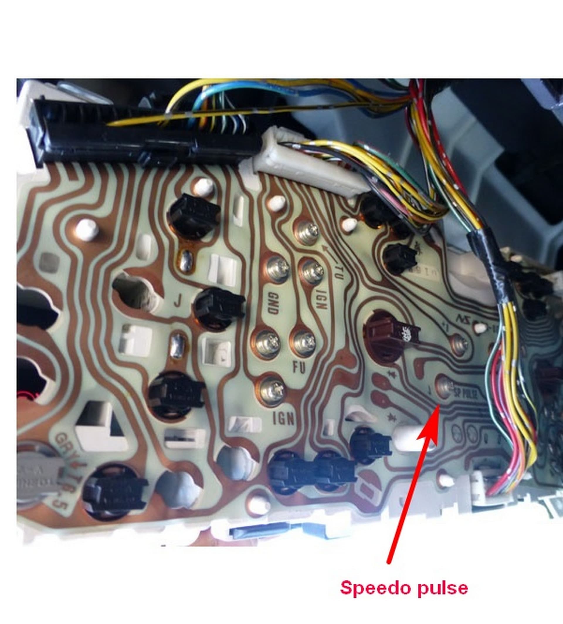
The LCD in the instrument panel can't be replaced so you have to put the replacement in an enclosure and mount it somewhere on the dash. There are a few mods you have to make to hook it all up. The speed sensor is on the front of the gearbox and has a red/yellow wire running to the dash. The sensor generates 2550 pulses per kilometre.
There is a good instruction of the Delica Club website showing how to remove the cluster and the speedo pulse connection is shown in the photo below.


You will need to make up a circuit board with a 12v to 5v regulator on it. I use an LM7805 which is overkill - it can supply 1A @ 5v. I tried an LM78L05 it can supply 100mA but the ESP32 draws more than that at startup so it caused problems. In addition you will need a Schmidt trigger (I use a Texas Instruments74C14 IC) to convert the pulse sine wave to a square wave. I use that to trigger an ISR on the rising edge to increment the pulse counter. You will also need an FRAM breakout board to store the pulse count - any other type of memory will 'wear out' in about 10,000K.
The TTGO was handy being in a single package but I have gone to an ESP32 D1 Mini and a TZT LCD 1.3" connected via SPI. It's also cheaper.

There is plenty of room on the FRAM to store service data and I intend to display prompts for service in the blue square below the odometer readings on startup.

I have two versions of the sketch:
ESP32 D1 Mini

#include "freertos/FreeRTOS.h"
#include "freertos/task.h"
#include "driver/gpio.h"

#include <FRAM.h>

#include <TFT_eSPI.h>
#include <SPI.h>
#include <Wire.h>

TFT_eSPI tft = TFT_eSPI();       // Invoke custom library

char buff[512];
int vref = 1100;
int btnCick = false;

// I2C stuff
const gpio_num_t GPIO21SDA = GPIO_NUM_21;
const gpio_num_t GPIO22SCL = GPIO_NUM_22;
FRAM fram = FRAM();
#define FRAM_ADDR 0x50  // the default address!
uint16_t addr = 2;
unsigned int tusec;

bool bFirst = true; // Used to display info on first loop only

struct SavedData {
unsigned int iPulses;
unsigned int iODO;
unsigned int iTrip;
};
//struct SavedData Odometer = {1908790 * 255, 1908790, 0};
struct SavedData Odometer;
int num = 0;
 
String sOdo = "";
String sTrip = "";


void IRAM_ATTR GPIO_ISR()
{
   Odometer.iPulses++;
}


// Speedo pulse stuff
unsigned int duration;
int PulseCore = 0;
int iNeg = 0;

boolean bUpdateDisp = true;
boolean bResetTrip = false;
static int PulsePin = 35;
static int TripResetPin = 33;

static int TestModePin = 34;
long timeout = 1000000; //One second
int triped; // trip reset duration
bool bTrip = true;
int testMode; // test mode duration
bool bTest = false;

void Task_Pulse( void * pvParameters ) {
static bool bFirst = true;
static unsigned int iOldPulses = 0;

  //handle pulses
  Serial.print("Pulse task running on Core: ");
  Serial.println(xPortGetCoreID());

  while (true) {
    if (Odometer.iPulses != iOldPulses) {
      Serial.print("new pulse count: ");
      Serial.println(Odometer.iPulses);
      iOldPulses = Odometer.iPulses;
  
      if (!(Odometer.iPulses % 255)) {
        Odometer.iODO++;
        Odometer.iTrip++;
        bUpdateDisp = true;
  //        Serial.println("Pulse 255");
      }

        // Write to FRAM via I2C
        num = fram.writeObject(addr, Odometer);
    } else {      
      delay(5);
    }
  }
}

void Trip_Reset( void * pvParameters ) {
  //handle trip reset
  delay(200);
  Serial.print("Trip reset task running on Core: ");
  Serial.println(xPortGetCoreID());

  while (true) {
  triped = digitalRead(TripResetPin);
    if (triped == 0) {
      if (bTrip) {
        Serial.println("Trip reset pressed.");
        bTrip = false;
        Odometer.iTrip = 0;
        bUpdateDisp = true;
      }
    } else {
      bTrip = true;
    }
    
    delay(300);
  }
}
  
void Task_Disp( void * pvParameters ) {
  //handle Disp[lay
  Serial.print("Display task running on Core: ");
  Serial.println(xPortGetCoreID());

  while (true) {
    if (bUpdateDisp) {
      bUpdateDisp = false;
      
      tft.setTextColor(TFT_GREEN, TFT_BLACK);
      sOdo = format_Num(Odometer.iODO);
//      long tus = -micros();
      tft.drawString(sOdo, tft.width() / 2,50);
      tft.setTextColor(TFT_BLUE, TFT_BLACK);
      sTrip = Pad_Trip(Odometer.iTrip);
      tft.drawString(sTrip, tft.width() / 2,110);
//      tus += micros();
    }    
    delay(70);
  } 
}

void setup() {
  Serial.begin(115200);
  while (!Serial) {delay(100);}
  Serial.print("setup() running on core ");
  Serial.println(xPortGetCoreID());

  Serial.println();
  Serial.println("ESP32_Odometer");
  
  pinMode(PulsePin, INPUT);
  pinMode(TripResetPin, INPUT);
  pinMode(TestModePin, INPUT);
  pinMode(LED_BUILTIN, OUTPUT);
  flash(2, 200);

  Serial.println("Attaching interupt: RISING");
  attachInterrupt(PulsePin, GPIO_ISR, RISING);
  Serial.println("Attached interupt: RISING");

  //Initialise screen
  Serial.println("Initialising tft");
  tft.init();
  tft.setRotation(0);
  tft.setCursor(0, 0);
  tft.setTextDatum(MC_DATUM);  
  tft.setTextColor(TFT_GREEN, TFT_BLACK);
  tft.fillScreen(TFT_BLACK);
  tft.setTextDatum(MC_DATUM);
  tft.setTextSize(3);

  tft.drawLine(0, 0, 239, 0, TFT_RED);
  tft.drawLine(239, 0, 239, 134, TFT_RED);
  tft.drawLine(239, 134, 0, 134, TFT_RED);
  tft.drawLine(0, 134, 0, 0, TFT_RED);

  tft.drawLine(0,141, 239, 141, TFT_BLUE);
  tft.drawLine(239, 141, 239, 239, TFT_BLUE);
  tft.drawLine(239, 239, 0, 239, TFT_BLUE);
  tft.drawLine(0, 239, 0, 141, TFT_BLUE);

  Start_FRAM();

  tft.setTextColor(TFT_GREEN, TFT_BLACK);
  tft.drawString("Odometer", tft.width() / 2,17);  
  tft.setTextColor(TFT_BLUE, TFT_BLACK);
  tft.drawString("Trip", tft.width() / 2,78);
  tft.setTextColor(TFT_GREEN, TFT_BLACK);
  Serial.println("Initialised tft");

  delay(200);
    
  Serial.println("Display Task Starting.");
  xTaskCreatePinnedToCore(
    Task_Disp,
    "Display",
    10000,
    NULL,
    1,
    NULL,
    1);
  Serial.println("Display created OK");
  
  Serial.println("Trip reset Task Starting.");
  xTaskCreatePinnedToCore(
    Trip_Reset,
    "Trip reset",
    1000,
    NULL,
    1,
    NULL,
    1);
  Serial.println("Trip_Reset created OK");
  
  Serial.println("Pulse Task Starting.");
  xTaskCreatePinnedToCore(
    Task_Pulse,   /* Function to implement the task */
    "Task_Pulse", /* Name of the task */
    10000,         /* Stack size in words */
    NULL,          /* Task input parameter */
    0,             /* Priority of the task */
    NULL,          /* Task handle. */
    PulseCore);  /* Core where the task should run */
  Serial.println("Task_Pulse created OK");
}

void loop() {
  if (bFirst) {
    Serial.print("loop() running on core ");
    Serial.println(xPortGetCoreID());
    bFirst = false;
  }

  testMode = digitalRead(TestModePin);
  if (testMode == 0) {
    //Toggle between test mode and real mode
    Serial.println("Test mode toggled");
    bTest = !bTest;
    delay(500);
    while (digitalRead(TestModePin) == 0) delay(300);
  }

  if (bTest) {
    Odometer.iPulses++;
//    tusec = micros();
    num = fram.writeObject(addr, Odometer);
//    tusec = micros() - tusec;
//    Serial.print("FRAM write time: ");
//    Serial.print(tusec);
//    Serial.println(" µSec.");
  
    if (!(Odometer.iPulses % 255)) {
      Odometer.iODO++;
      Odometer.iTrip++;
      bUpdateDisp = true;
//      Serial.println("Pulse 255");
    }
  }
    
  delay(5);
}

String Pad_Trip ( unsigned int iTrip) {
  String s = format_Num(iTrip);
  int i = s.length();
  while (i++ < 9) {
    s = " " + s;
  }
  return s;
}

void Start_FRAM () {
  Wire.begin();
  Wire.setClock(1000000);

  if (fram.begin(FRAM_ADDR) == 0) {
    Serial.println("Found I2C FRAM");
//  Write is for initial setup only.
//**Remove after testing
//    num = fram.writeObject(0x00, addr);
//    tusec = -micros();
//    num = fram.writeObject(addr, Odometer);
//    tusec += micros();
//    Serial.print("Write time = ");
//    Serial.print(tusec);
//    Serial.println(" µSec.");
//    
//    Serial.print("Wrote Odometer string with ");
//    Serial.print(num);
//    Serial.println(" bytes.");

    fram.readObject(0x00, addr);
    tusec = -micros();
    fram.readObject(addr, Odometer);
    tusec += micros();
    Serial.print("Read time = ");
    Serial.print(tusec);
    Serial.println(" µSec.");
    
    Serial.print("Read Odometer string value: ");
    Serial.print(Odometer.iPulses);
    Serial.print("; ");
    Serial.print(Odometer.iODO);
    Serial.print("; ");
    Serial.println(Odometer.iTrip);
  } else {
    Serial.println("I2C FRAM not found ... check your connections?\r\n");
    tft.setTextSize(4);
    tft.setTextColor(TFT_RED, TFT_BLACK);
    tft.drawString("FRAM ERROR", tft.width() / 2,70);
    while (1) delay(10);
  }  
}

//Comma format of decimal to one decimal place
String format_Num (unsigned int num) {
int rem;
int quotient;
String sNum ="";

  if (num < 10) {
    return "0." + String(num);  
  } else {
    rem = num % 10;
    sNum = "." + String(rem);
    quotient = num /10;
    while (quotient > 1000) {
      rem = quotient % 1000;
      sNum = "," + String(rem) + sNum;
      quotient = quotient /1000;
    }
    return quotient + sNum;
  }
}

void flash1 (int duration) {
  digitalWrite(LED_BUILTIN, HIGH);   // sets the LED on
  delay(duration);              // waits for duration
  digitalWrite(LED_BUILTIN, LOW);    // sets the LED off
  delay(duration);              // waits for duration
}

void flash (int flashes, int duration) { // MaX 1 second flash
  for (int x = 0; x < flashes; x++) {
    flash1(duration);
  }
}

and The normal ESP32 DevKit 1

#include "freertos/FreeRTOS.h"
#include "freertos/task.h"
#include "freertos/event_groups.h"

#include <driver/i2c.h>
#include <Wire.h>
#include <Adafruit_SSD1306.h>
#include <splash.h>
#include <Adafruit_FRAM_I2C.h>

#define SCREEN_WIDTH 128 // OLED display width, in pixels
#define SCREEN_HEIGHT 64 // OLED display height, in pixels
// Declaration for an SSD1306 display connected to I2C (SDA, SCL pins)
Adafruit_SSD1306 display(SCREEN_WIDTH, SCREEN_HEIGHT, &Wire, -1);
Adafruit_FRAM_I2C fram = Adafruit_FRAM_I2C();

bool bFirst = true; // Used to display info on first loop only

struct SavedData {
unsigned int iPulses;
unsigned int iODO;
unsigned int iTrip;
};
struct SavedData Odometer = {1908790 * 255, 1908790, 0};
int num = 0;
 
String sOdo = "";
String sTrip = "";

// Speedo pulse stuff
int PulseCore = 0;
int iNeg = 0;

boolean bUpdateDisp = true;
boolean bResetTrip = false;
static int PulsePin = 15;
static int TripResetPin = 13;
long timeout = 1000000; //One second
unsigned long duration; // pulse duration
unsigned long triped; // trip reset duration

// I2C stuff
const gpio_num_t GPIO21SDA = GPIO_NUM_21;
const gpio_num_t GPIO22SCL = GPIO_NUM_22;

const int LEDpin = 2;      // LED pin

void Task_Pulse( void * pvParameters ) {
  //handle ODO pulses
  Serial.print("Pulse task running on Core: ");
  Serial.println(xPortGetCoreID());

  while (true) {
    duration = pulseIn(PulsePin, HIGH, timeout);
    if (duration > 0) {
      Odometer.iPulses++;

      if (!(Odometer.iPulses % 255)) {
        Odometer.iODO++;
        Odometer.iTrip++;
        bUpdateDisp = true;
        Serial.println("Pulse 255");
      }
      
// Write to EEPROM or FRAM vis I2C
      num = fram.writeObject(0x00, Odometer);
      Serial.print("Wrote Odometer string with ");
      Serial.print(num);
      Serial.println(" bytes");
    } else {      
      delay(1);
    }
  }
}

void Task_Disp( void * pvParameters ) {
  //handle Disp[lay
  Serial.print("Display task running on Core: ");
  Serial.println(xPortGetCoreID());

  while (true) {
    if (bUpdateDisp) {
      bUpdateDisp = false;
      //Serial.println("Clearing display");
      display.clearDisplay();
      display.setTextSize(1);
      display.setCursor(0, 5);
      display.println("Odometer and Trip");
    
      display.setTextSize(2);
      //iOdo = iPulses / 255;
      sOdo = String(Odometer.iODO / 10) + "." + String(Odometer.iODO % 10);
      display.setCursor(20, 17);
      display.print(sOdo);
      sTrip = Pad_Trip(Odometer.iTrip);
      display.setCursor(20, 39);
      display.print(sTrip);
      display.display();
    }
    
    delay(100);
  } 
}

void setup() {
  Serial.begin(115200);
  while (!Serial) {}
  Serial.print("setup() running on core ");
  Serial.println(xPortGetCoreID());

  Serial.println();
  Serial.println("ESP32_Odometer");
  
  pinMode(PulsePin, INPUT);
  pinMode(TripResetPin, INPUT);

  pinMode(LEDpin, OUTPUT);
  flash(2, 200);
  
  if (fram.begin()) {
    Serial.println("Found I2C FRAM");
// Write is for initial setup only.
    num = fram.writeObject(0x00, Odometer);
    Serial.print("Wrote Odometer string with ");
    Serial.print(num);
    Serial.println(" bytes.");

    fram.readObject(0x00, Odometer);
    Serial.print("Read back string value: ");
    Serial.print(Odometer.iPulses);
    Serial.print("; ");
    Serial.print(Odometer.iODO);
    Serial.print("; ");
    Serial.println(Odometer.iTrip);

} else {
    Serial.println("I2C FRAM not identified ... check your connections?\r\n");
    Serial.println("Will loop in case this processor doesn't support repeated start\r\n");
    while (1);
  }
  
  Serial.println("Connecting to display");
  if(!display.begin(SSD1306_SWITCHCAPVCC, 0x3C)) { // Address 0x3D for 128x64
    Serial.println(F("SSD1306 allocation failed"));
    for(;;); // Don't proceed, loop forever
  }
  Serial.println("Display connected to I2C");
  delay(200); // Let things settle down
  display.clearDisplay();
  display.setTextSize(1);
  display.setTextColor(WHITE);
  bUpdateDisp = true;

  Serial.println("Display Task Starting.");
  xTaskCreatePinnedToCore(
    Task_Disp,
    "Display",
    10000,
    NULL,
    1,
    NULL,
    1);
  Serial.println("Display created OK");

  Serial.println("Pulse Task Starting.");
  xTaskCreatePinnedToCore(
    Task_Pulse,   /* Function to implement the task */
    "Task_Pulse", /* Name of the task */
    10000,         /* Stack size in words */
    NULL,          /* Task input parameter */
    0,             /* Priority of the task */
    NULL,          /* Task handle. */
    PulseCore);  /* Core where the task should run */
  Serial.println("Task_Pulse created OK");
}

void loop() {
  if (bFirst) {
    Serial.print("loop() running on core ");
    Serial.println(xPortGetCoreID());
    bFirst = false;
  }
  // Test for trip reset button pressed
  triped = pulseIn(TripResetPin, HIGH, 3000);
  if (triped > 0) {
    Serial.println("Trip reset pressed.");
    Odometer.iTrip = 0;
    bUpdateDisp = true;
  }
  
  delay(3000);
  
  //Test fiddle
  Odometer.iPulses += 255;
  bUpdateDisp = true;
}

String Pad_Trip (int iTrip) {
  String s = String(iTrip / 10) + "." + String(iTrip % 10);
  int i = s.length();
  while (i++ < 8) {
    s = " " + s;
  }
  return s;
}

void flash1 (int duration) {
  digitalWrite(LEDpin, HIGH);   // sets the LED on
  delay(duration);              // waits for duration
  digitalWrite(LEDpin, LOW);    // sets the LED off
  delay(duration);              // waits for duration
}

void flash (int flashes, int duration) { // MaX 1 second flash
  for (int x = 0; x < flashes; x++) {
    flash1(duration);
  }
}

Feel free to use it if you wish and alter it in any way it suits you.

PS. You will need to setup a custom library for the TZT to specify the screen params for whatever LCD you choose. If you use the same LCD as me I will send you the custom library changes.

Thanks so much, you explaind really well... i'll try next week and i'll let you know after i order my the other few bits, like the regulator.
And you did place the TTGO under the cluster glass? or outside for have easy configuration?

The 7805 sounds good but it will not survive the possible transients in an automotive electrical system. You should look up load dump etc to see what you are against. There is also reverse battery and double battery jump to name a few.

If it continues to work reliably I will mount it in the coin slot space. I don't look at it that often but is quite visible there.


That was the reason for using a square LCD and the smaller footprint of the ESP32 D1 Mini.
I forgot to mention I put a 1kΩ resister between the speedo pulse and the Schmidt trigger input - I don't want to draw too much current from the pulse, it is used for engine control functions. I also put a 220µf capacitor across the LM7805 output.

Thanks for pointing that out. I haven't made a reverse connection in my sixty years of motoring - yet :grinning: But I suppose a diode would fix that. As for transients, they are more of a concern; when cranking the engine low voltage is a problem and can cause the ESP32 to fail to start. I haven't yet had an over voltage problem. I believe the LM7805 will cope with up to 35v. The van's ECU must have over voltage protection so maybe I could find a power source there. Unfortunately I have been unable to find an English version of the L400 wiring diagram - something that would very useful if I could.

Sorry for the late reply, but i miss your message... yes i need to figurate out where to place, i order the missing parts last week from banggod, so probably i need to wait 20 days. Which functions did you setup in the screen? or did you setup just for the odometer reading?
Cheers

The code I sent you displays the odometer reading and a trip reading. The trip reading needs a momentary push button to reset it. The TTGO has two push buttons on it and I used one of them for that version. The Wemos ESP32 D1 Mini uses a GPIO pin to reset the trip.
You will notice there is a commented out section in the code that needs to be run once to initialise the FRAM when you setup your current odometer value. (Or you could write a separate sketch to initialise the FRAM)

Could you clarify this output? What is the "Odometer string 112 bytes"? According to time it's not like writing 112 bytes, it's more like writing 12 bytes for I2c speed 400 MHz. Could you explain what these numbers mean?
Are you store the odometer to the FRAM as string? As I see in the code you use the structure of three integers, why do you not store it as is?

I'm using the ttgo so I should not have any problems with buttons... thank you so much for your help soon as I have all the parts ill contact you. I'm thinking to buy a 3d printer or make something at my work with my cnc as support for the screen. If you need one pretty happy to make for you.
Thanks

Although I write just three integers to the FRAM the write string includes all the control characters that get transferred across the I2C interface to complete the write sequence which is really done byte by byte.

The printout of the integers read back is converted to a string by my sketch.

I was hoping to get an FRAM board that uses SPI to see how that interface performs as I suspect it would be much faster still, but they aren't that cheap when compared to the I2C FRAM price. So I haven't bothered going down that path.