[Solved] Shifting 21 bytes for RGB 7segment display

First post, hope I read all the rules correctly.

I have an RGB 7-segment display that I want to program as a clock. I designed it myself but did not realize the complexity of the code with the design that I have.

I'm going to do my best to explain everything so bear with me.

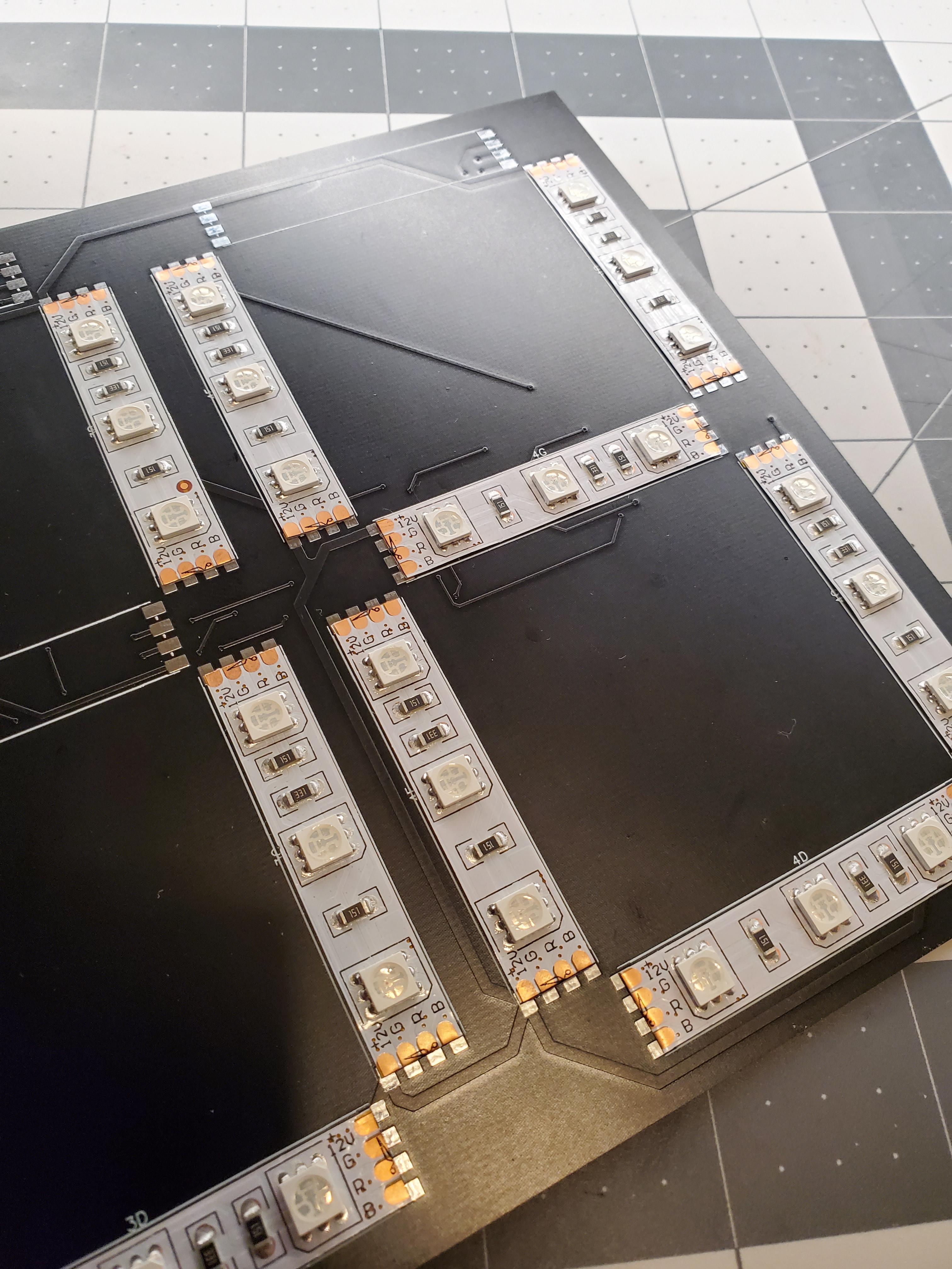
It has 6x 16-bit shift registers whose outputs are connected to short strips of those LED strip lights you can buy on Amazon. The main MCU is an Arduino Nano that is plugged in the back of the panel. (The shift registers are connected to the SPI pins so if i can use that it would be nice).

The problem I'm having is I need 21 bits for each digit. 7 segments * 3 colors. I have the data for the digits saved in an array:

const __uint24 blueNumbers[10]{
  0b001001001001001001000,
  0b000001001000000000000,
  0b001001000001001000001,
  0b001001001001000000001,
  0b000001001000000001001,
  0b001000001001000001001,
  0b001000001001001001001,
  0b001001001000000000000,
  0b001001001001001001001,
  0b001001001001001000001
};

with the first 3 bits left-padded with 0's.

The segments are connected in order: a(red) -> a(blue) -> a(green) -> b(red) -> b(green) -> b(blue) etc... where the a,b,c,d,e,f,g are the 7 segments. Some shift registers share the same digits.
E.g. a red number 4 would be 0b000 100 100 000 000 100 100 (I broke it up to show how each segement is 3 bits corresponding to RGB respectively.) I need to somehow cut off the first 3 bits and combine the 4 digits into 6x 16bit or 12x 8bit values so that I can shift the data out fast enough that the display doesn't flicker.

I tried doing this using 16bit variables and bit-shifting but it's not working and I cant figure out what im doing wrong. Is there an easy way to cut off the first 3 bits and create a sequence of bytes with the necessary values to shift out? I need the first 3 cut off because otherwise it shifts 0's when I don't want it to.

TL;DR: I need to cut off 3 MSB's from 4x 24-bit values and combine them into 6x words or 12x bytes. (I know the number of bits doesn't add up so I need the last 12 bits padded with 0's or whatever as they arent connected to any LED's).
OR I need to shift 21 bits using SPI which I dont think is possible because of the architecture of the SPI preipherals. (modified shiftOut as last resort as it causes flicker)

#include <SPI.h>
#include <Wire.h>

#define I2C_ADDR 104

const int latch = 10; // Pin assignment
const int outputEnable = 7; // ^^

uint16_t sr1;
uint16_t sr2;
uint16_t sr3;
uint16_t sr4;
uint16_t sr5;
uint16_t sr6;

const __uint24 blueNumbers[10]{
  0b001001001001001001000,
  0b000001001000000000000,
  0b001001000001001000001,
  0b001001001001000000001,
  0b000001001000000001001,
  0b001000001001000001001,
  0b001000001001001001001,
  0b001001001000000000000,
  0b001001001001001001001,
  0b001001001001001000001

};

void setup() {
  Wire.begin();
  Serial.begin(9600);
  pinMode(latch, OUTPUT);
  pinMode(outputEnable, OUTPUT);
  pinMode(11, OUTPUT);
  pinMode(13, OUTPUT);
}

void loop() {
  // Turn LED's off
  digitalWrite(outputEnable, HIGH);
  
  // Datashift
  createDisplayBytes(1,2,3,4); // Testing using 1-4 for now
  shiftOut(11, 13, LSBFIRST, sr6);
  shiftOut(11, 13, LSBFIRST, sr5);
  shiftOut(11, 13, LSBFIRST, sr4);
  shiftOut(11, 13, LSBFIRST, sr3);
  shiftOut(11, 13, LSBFIRST, sr2);
  shiftOut(11, 13, LSBFIRST, sr1);

  // Latch
  digitalWrite(latch, HIGH);
  digitalWrite(latch, LOW);
  // Turn LED's on
  digitalWrite(outputEnable, LOW);
  
  delay(250);
}

void createDisplayBytes(int num1, int num2, int num3, int num4) {
  sr1 = blueNumbers[num1];
  sr2 = (blueNumbers[num1] >> 16) + (blueNumbers[num2] << 5);
  sr3 = (blueNumbers[num2] >> 11) + (blueNumbers[num3] << 10);
  sr4 = (blueNumbers[num3] >> 6) + (blueNumbers[num4] << 15);
  sr5 = blueNumbers[num4] >> 1;
  sr6 = blueNumbers[num4] >> 17;
}

void readalltoconsole() {
  int i;
  Wire.beginTransmission(I2C_ADDR); // transmit to device #44 (0x2c)
  Wire.write(byte(0x00));
  Wire.endTransmission();
  
  Wire.requestFrom(104, 8);
  if (8 <= Wire.available()) { // if eight bytes were received
    for(int j = 0; j < 8; j++){
      int val = Wire.read();
      Serial.print("0");
      Serial.print(j);
      Serial.print("h = ");
      for(int i = 7; i >= 0; i--)
        Serial.print(bitRead(val,i));
      Serial.println();
    }
  }
  Serial.println();
  Serial.println();
}

Schematic_RGB_Clock.pdf (217 KB)

bears0:
First post, hope I read all the rules correctly.[...]I tried doing this using 16bit variables and bit-shifting but it's not working and I cant figure out what im doing wrong.

We can't either, it would be guesswork. Please post your code in code tags.

Added code + Schematic. It took me a min to find how to properly format the code...

with the first 3 bits left-padded with 0's

?

Are we talking 21 bits or 21 bytes here?
I'm confused.

TheMemberFormerlyKnownAsAWOL:
Are we talking 21 bits or 21 bytes here?
I'm confused.

-> 21 bits <- Each digit is 7 segments * 3 colors = 21 LED's to control with the shift registers.

Sorry. I realize this is confusing. Took me a bit to wrap my head around it too.

The process I'm thinking of goes like this.

I want to somehow combine 21-bits(digit 4) + 21-bits(digit 3) + 21-bits(digit 2) + 21-bits(digit 1).
Shift data LSBFIRST.

BUT, broken up into byte segments so I can load the SPI register and let the SPI peripheral handle the shifting to speed things up.

I already have the data stored in 24-byte constants.
The first 3 bits are not used as I only need 21 bits to control one digit.
Imagine cutting out the first 3 bits of every 24-bit constant. Then put them all together and select every 8 bits. It's easy to grab a high and low byte, but since there's 21 bits I get a remainder of 5 which means i need 5 bits from digit1 + 3 bits from digit2 to combine into a byte.

Hopefully this makes sense to you guys/gals.

I still find it very confusing.

anyhow with the code which you post in post#1, are your LEDs illuminating the way you want?

could you also clarify:

are you trying to to cycle the 'display' red, blue, green?

OR

are you trying to cycle the individual digit segments red, blue, green?

The LED's light up but not in the correct sequence. For right now I just want to light them up blue. I took out the arrays that hold the red and green data because it made it really long and I hadn't fully implemented that part anyways.

A 7-segment display has a generic segment designation from "a" to "g". Each segment has a Red, green and blue color. Bits 1 through 16 of the first led driver register are connected to a-red, a-green, a-blue, b-red, b-green, b-blue, c-red, c-green, c-blue, d-red, d-green, d-blue, e-red, e-green, e-blue, f-red. (Format is segment-color) This order follows for the rest of the 6 cascading shift register drivers.

If I could do It over again I would've rearranged the order In which the LEDs are connected to make programming easier but since it was $50 for 5 PCB's I am trying to make these work first.

Thanks for the help on this

sherzaad:
I still find it very confusing.

anyhow with the code which you post in post#1, are your LEDs illuminating the way you want?

could you also clarify:

are you trying to to cycle the 'display' red, blue, green?

OR

are you trying to cycle the individual digit segments red, blue, green?

Yes they light up, but in a random way. They dont flash or change.

I would like to have control over the color of the entire display. Not individual segments.

Right now I just want to be able to pass 4 numbers into a function and that function will either shift out the data required to display those numbers, or save the data in global byte variables that I can shift out in my main loop. The reason I want 4 numbers is because I will be getting those numbers from an RTC

You’ve done really well with your first post, the only suggestion would be to post the schematic as an inline image,mor attached JPG because it’s more portable.

+Karma for trying!

lastchancename:
You’ve done really well with your first post, the only suggestion would be to post the schematic as an inline image,mor attached JPG because it’s more portable.

+Karma for trying!

I'm not sure what you mean by inline... do you mean embedded in the post so you don't have to download?
Yeah I didn't think about how a PDF might be difficult to navigate if you open with a web browser. I just thought it would give better clarity than a jpg since its in vector form

Here is a schematic on one page:

and a quick hand drawn diagram:

and a digit before soldering:

I think part of the problem is you are using shiftOut(), which only takes 8 bits, to shift out a 16-bit value. You will have to either 'createDisplayBytes()' into 12 bytes or use two shiftOut() calls for the two bytes of each 16-bit value.

This version of loop() should light one color in each segment in order and hen do the same on the next color. It might be a good test to see if your wiring is correct.

void loop()
{
  static byte bitPosition = 0;
  
  // Turn LED's off
  digitalWrite(outputEnable, HIGH);


  // Send out 12 bytes (96 bits) of data
  for (int index = 0; index < 12; index++)
  {
    if (bitPosition >= (index * 8) && bitPosition < ((index + 1) * 8))
      shiftOut(11, 13, LSBFIRST, 1 << (index % 8));
    else
      shiftOut(11, 13, LSBFIRST, 0);
  }


  // Latch
  digitalWrite(latch, HIGH);
  digitalWrite(latch, LOW);


  // Turn LED's on
  digitalWrite(outputEnable, LOW);


  delay(250);


  bitPosition += 3; // Skip the other colors (change to 21 to do the same segment of each digit)
  if (bitPosition >= 96)
  {
    bitPosition -= 96;
    bitPosition++; // Next color
  }
}

johnwasser:
I think part of the problem is you are using shiftOut(), which only takes 8 bits, to shift out a 16-bit value. You will have to either 'createDisplayBytes()' into 12 bytes or use two shiftOut() calls for the two bytes of each 16-bit value.

Thanks!!! I had switched back and forth so much that I forgot that the original verison of shiftout was 8 bits. sendData is my modified version of shiftout.

The LED's still dont light up in order with your program but thanks for it because I can use it for testing. I'm still really confused as to why your code lights up all the segments in a wacky order. I'm going to double check the schematic and make sure I didnt screw something up there. I do know that shifting out all 1's lights up all the LED's so I know theyre connected, but maybe something got screwed up halfway and is throwing everything off. (Should be connected how I explained but I am only human...)

I modified your code to also printout a representation of the bits being sent because it doesn't seem to work and I think this is because the last 12 bits in the last shift register are not connected to anything and its throwing off the order.

Here is the terminal output. (after using a program to flip left-right to put the first data sent on the right)

000000000000000000000000000000000000000000000000000000000000000000000000000000000000000000000001
000000000000000000000000000000000000000000000000000000000000000000000000000000000000000000000001
000000000000000000000000000000000000000000000000000000000000000000000000000000000000000000000001
000000000000000000000000000000000000000000000000000000000000000000000000000000000000001000000000
000000000000000000000000000000000000000000000000000000000000000000000000000000000000001000000000
000000000000000000000000000000000000000000000000000000000000000000000000000001000000000000000000
000000000000000000000000000000000000000000000000000000000000000000000000000001000000000000000000
000000000000000000000000000000000000000000000000000000000000000000000000000001000000000000000000
000000000000000000000000000000000000000000000000000000000000000000001000000000000000000000000000
000000000000000000000000000000000000000000000000000000000000000000001000000000000000000000000000
000000000000000000000000000000000000000000000000000000000000000000001000000000000000000000000000
000000000000000000000000000000000000000000000000000000000001000000000000000000000000000000000000
000000000000000000000000000000000000000000000000000000000001000000000000000000000000000000000000
000000000000000000000000000000000000000000000000001000000000000000000000000000000000000000000000
000000000000000000000000000000000000000000000000001000000000000000000000000000000000000000000000
000000000000000000000000000000000000000000000000001000000000000000000000000000000000000000000000
000000000000000000000000000000000000000001000000000000000000000000000000000000000000000000000000
000000000000000000000000000000000000000001000000000000000000000000000000000000000000000000000000
000000000000000000000000000000000000000001000000000000000000000000000000000000000000000000000000
000000000000000000000000000000001000000000000000000000000000000000000000000000000000000000000000
000000000000000000000000000000001000000000000000000000000000000000000000000000000000000000000000
000000000000000000000000000000010000000000000000000000000000000000000000000000000000000000000000
000000000000000000000000000000010000000000000000000000000000000000000000000000000000000000000000
000000000000000000000000000000010000000000000000000000000000000000000000000000000000000000000000
000000000000000000000010000000000000000000000000000000000000000000000000000000000000000000000000
000000000000000000000010000000000000000000000000000000000000000000000000000000000000000000000000
000000000000000000000010000000000000000000000000000000000000000000000000000000000000000000000000
000000000000010000000000000000000000000000000000000000000000000000000000000000000000000000000000
000000000000010000000000000000000000000000000000000000000000000000000000000000000000000000000000
000010000000000000000000000000000000000000000000000000000000000000000000000000000000000000000000
000010000000000000000000000000000000000000000000000000000000000000000000000000000000000000000000
000010000000000000000000000000000000000000000000000000000000000000000000000000000000000000000000

EDIT: I modified it to shift out
10000...000
01000...000
00100...000
00010...000
00001...000

and it operates as expected lighting up each segment in an RGB sequence. I just need a way to create all twelve bytes using the segment data. I have tabulated it all in Excel

In case anyone is interested in my most likely one of a kind solution, here it is.

I'm not sure what I had done wrong with the bit shifting calculations before but I rewrote the data and made a simple chart that told me what bits needed to go where.

When I put it into code, I noticed that initially I somehow got everything backwards. The new code worked and I proceeded to add terminal control for changing the time, color, 12/24hr, and brightness.

Thank you everyone for your help!

Code is uploaded because it now exceeds the limit (still v0.1, but it works great for now)

RGBClockCode.cpp (14.2 KB)