Hi guys,
I just finished building my first single sided arduino (ver. 3) from here:
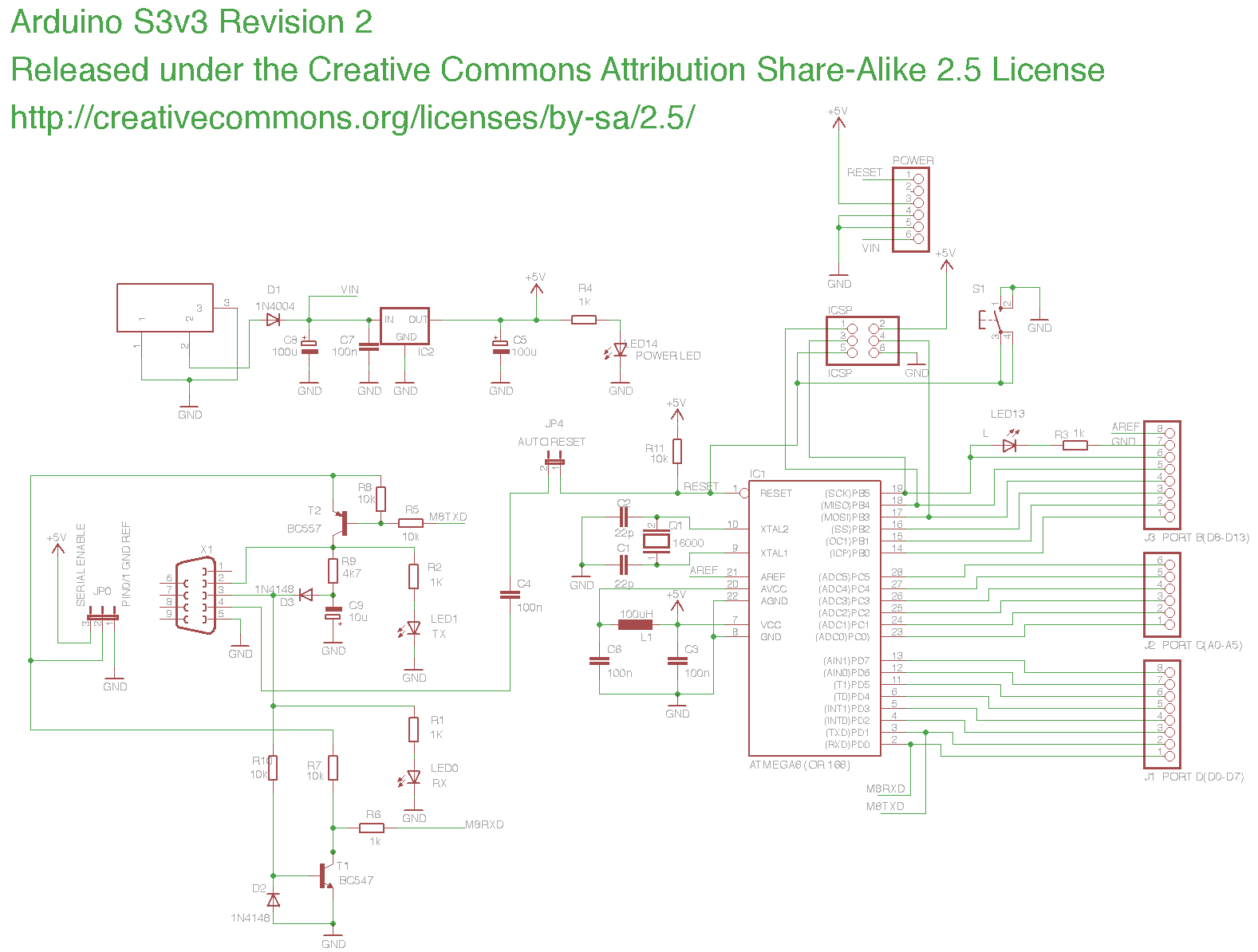
I built the board as described from scratch with toner transfer and soldererd all the parts listet together and checked that several times. The only difference is here, that I was not able to obtain an unpolarized electrolytic capacitor for the TTL to RS232 converter. This part was soldered as described in the schematic (which has not been updated by the way).
I bootloaded the ATMEGA 168 via an arduino uno and it seems to work correctly. When i power up my new board, the power led lights up. The PIN13 LED blinks. My conclusion from that is, that the power supply as well as the ATMEGA and supporting circutry (like the oscillator and the 22pif capacitors and so on) work correctly and that the bootloader was successfully burned.
There must be something wrong in the RS232<-> TTL converter. When I upload a sketch, there is a communication problem:
avrdude: stk500_getsync(): not in sync: resp=0x00 (In Arduino 1.5.7 I get avrdude: stk500_getsync() attempt 4 of 10: not in sync: resp=0x01)
I use a Prolific USB -> RS232 Cable (baudrate 19200) to connect the board. I tested it by programming a handheld radio and it seems to work correctly.
It does not matter how I set the jumpers (reset and serial enable). Also is switched the polarity of the capacitor c9 (just because of despair). I tried using the current arduino software as well as the older 1.0.6 with the Diecimila with ATMEGA 168 setting (and some other settings as well).
It must be something REALLY stupid. I checked all parts and also the routing of the board several times and I am thus pretty shure, that I did that correctly (although nobody is perfect)
I bootloaded the ATMEGA 168 via an arduino uno and it seems to work correctly.
Assuming this Uno belongs to you, try swapping the uC and see if the 168 works in the Uno.
The only difference is here, that I was not able to obtain an unpolarized electrolytic capacitor for the TTL to RS232 converter.
You should fix this... Especially if the 168 works in the Uno.
Homemade boards can have contamination which will throiw the crystal off freq or even prevent it from working. Inspect and clean the crystal area of the PCB.
The AVR line of 8-bit devices are extremely rugged. Ray's Projects
Ray
thank you very much for your ideas. Unfortunately my UNO is the newer version (with SMD µC), so I cannot exchange it.
I cleaned the whole board from soldering residues. This was unfortunately not the problem. The µC blinks the LED quite nicely however...
Could you comment a little more on the issue with the capacitor? In the manual, it is stated, stat using a polarized capacitor could only cause trouble, when the serial port is not in use. Could you explain to me, why this is a problem, when the serial port is in use? It should only be charged, wenn the RS232 is negative (State 1) due to the diode?!
Auto-reset works by connecting the DTR line to RESET through a capacitor and pulling it low thereby temporarily lowering RESET too.
The value of the 10K pull-up and the 0.1uF cap are designed to create a reset pulse with the appropriate high-low-high transition. Too much capacitance will cause the reset waveform to be malformed and too little capacitance will cause the reset waveform to be too narrow and potentially not go to signal ground.
Hmm in my schematic, C9 is a 10µF capacitor which (in my understanding) is used to generate the large negative voltage to transmit RS232 TRUE to the PC (by storing some current from the times, the computer transmits Rs232 TRUE).... Am i totally wrong? I think your answer is related to capacitor C4 and R11?
lukebo:
Hmm in my schematic, C9 is a 10µF capacitor which (in my understanding) is used to generate the large negative voltage to transmit RS232 TRUE to the PC (by storing some current from the times, the computer transmits Rs232 TRUE).... Am i totally wrong? I think your answer is related to capacitor C4 and R11?

