I am building a project that requires a stepper motor to turn something and so far it has worked great. recently we changed the design on the shaft the motor is turning and now it no longer works. I ran a bunch of tests on the circuit and found that it is not working as it should be. I built another circuit to test the motor to make sure that wasn't the problem and the second circuit works fine. I would really like to keep the original circuit. I can post code if needed but I know it works
cole:
I can post code if needed but I know it works
If you know the code works and if the motor was working before you "changed the design on the shaft" then it sounds like you have a mechanical problem.
As you have not told us what the change was ....
...R
the change i made is the drive chain is no longer a chain but rather a pulley. i think mechanically it works well because with this test circuit i made, the motor with the pulley turns just fine.
cole:
because with this test circuit i made,
I think you forgot to post the circuit diagram.
...R
here is a schematic of the breadboard. i'm not sure what the stepper motor driver is but i know it is one that has the step and direction pins.

That sort of diagram is almost impossible to interpret reliably. Just make a simple pencil drawing and post a photo of the drawing.
If you don't know what stepper motor driver you have then post a clear photo of it. If you don't know what it is, then how did you get it?
...R
cole:
I am building a project that requires a stepper motor to turn something and so far it has worked great. recently we changed the design on the shaft the motor is turning and now it no longer works. I ran a bunch of tests on the circuit and found that it is not working as it should be. I built another circuit to test the motor to make sure that wasn't the problem and the second circuit works fine. I would really like to keep the original circuit. I can post code if needed but I know it works
Clearly there is a difference between the two circuits, and that's where to look for answers.
The chip is a A4988 stepper motor driver and some more info can be found at this site:
Along with the chips datasheet at this site:
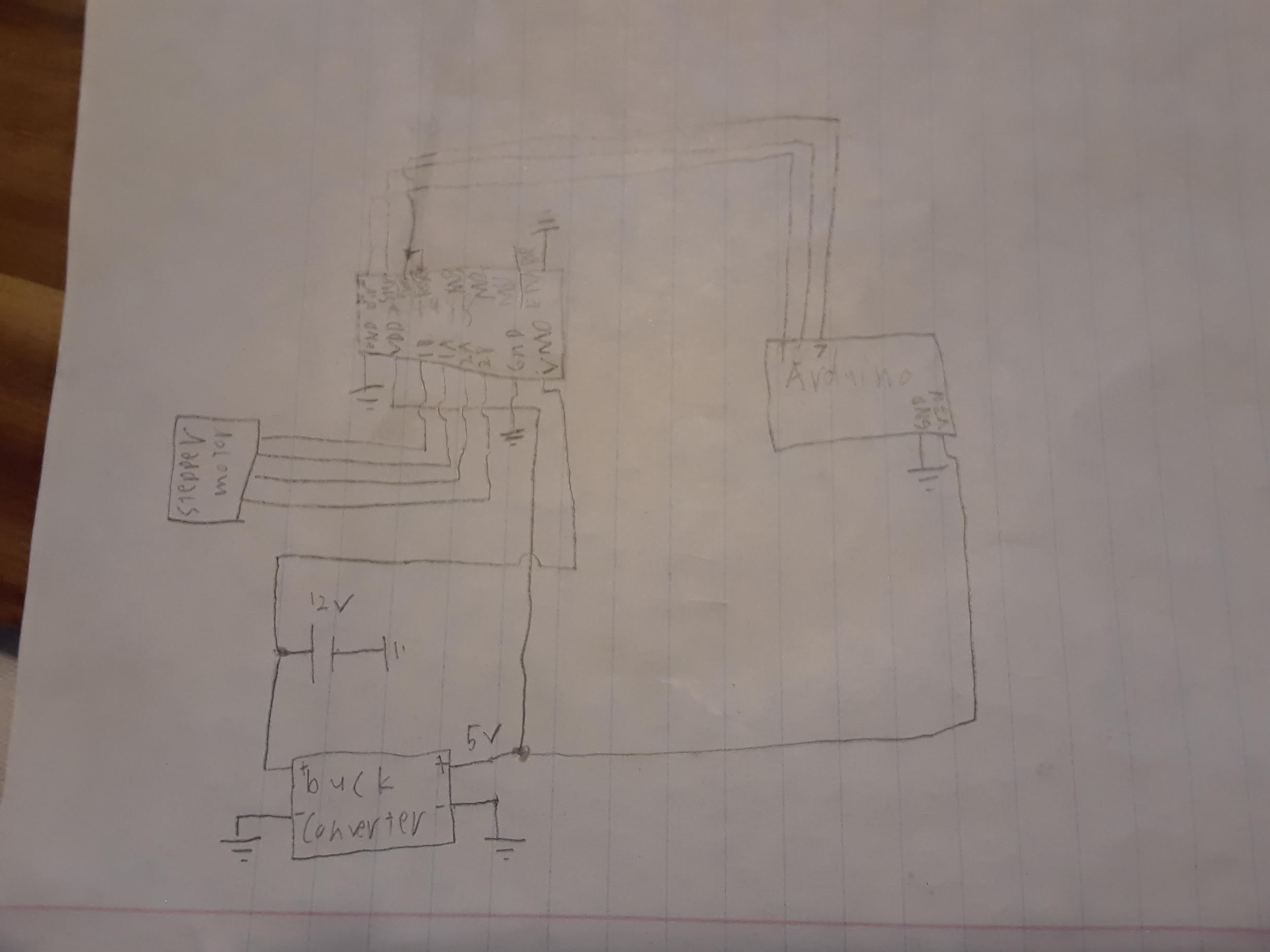
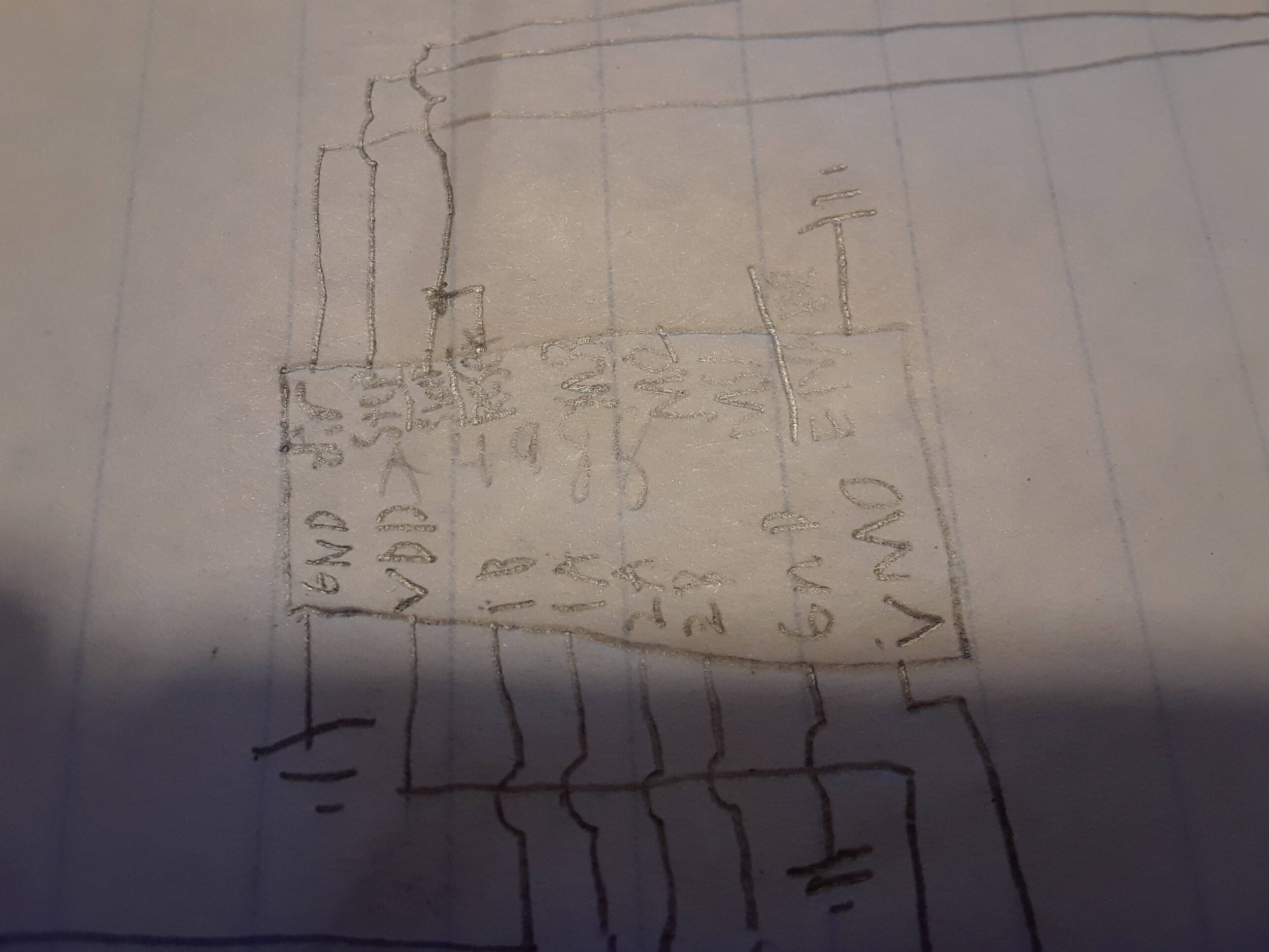
Attached are 2 pictures. The first is a hand drawn image of all motor related circuitry and the second is a close up of the driver chip on the paper.
I have done a bunch of testing with an oscilloscope on both the test circuit and on the original circuit. The only thing I noticed that is different is that the test circuit outputs very clean square waves where as the original circuit has very irregular waves. It almost looks like mains power interference.
Your drawing skills are fine but not so your photography. I can't read your photos.
...R
I resolved the problem and found it to be that the stepper motor driver chip had been fried. I'm guessing that I unplugged the stepper motor while it was running and that produced a large electrical spike. I'm not sure how high those spikes can get though.
I'm not sure how high those spikes can get though.
.. apparently high enough to kill your driver.
Lesson learnt: never connect or disconnect a motor while te circuit is powered.