I am building a synth with a library called Mozzi and it has a DUAL PWM OUTPUT with MIDI.
Here is the schematic:
The synth by itslef works fine, the audio output is very good.
The problem starts when I connect another device via MIDI INPUT, you can hear a very low frecuency wave that is made from the other synth's MIDI clock pulse. Also when a note gets received via MIDI in, it makes a click or crackle sound.
the MIDI signal interfering with the audio output is very thin but it's there.
tryed to do a RC low pass filter on VREF and AVCC but it does nothing to mute those click sounds.
Also if I take out the Atmega chip, the sound's still there if MIDI is being sent.
OK! I think I got it.
I placed a 1000uF capacitor between 9V and GND (power supply) and maybe another between 5V and GND (7805 voltage regulator) and the clicks noise got lowered a lot. It seems that the midi signals create a ripple in the power source.
I hope maybe 3000uF will silence that.
Thanks!
Thanks for answering grumpy Mike! I was hoping you did
Very good article.
I already placed 100nF capacitors on each IC but what I understood from your article is that those low value capacitors take care of high frecuency variations on the voltage but midi signals create a low frecuency ripple. The clock signal for example could be of about 40Hz.
Should I put 470uF or so capacitors on a few ICs? Or maybe just put a inductor with the capacitor on the power supply input?
Thanks again
Both are good strategies. I would not go with the inductor first unless you try to isolate different sections of the power distribution. That is isolate the analogue amplifiers from the digital parts.
You can also do the same thing with the grounds, group all the digital grounds to one common point, then all the analogue ones to a common point. Then connect these two points together with only one wire.
I tested it again and don't know what happened the other day, the capacitor on 9v and gnd doesn't prevents any noise.
I might have done a quick try the other day and was wrong about it lowering the midi noise.
I think this noise is there because of poor pcb design on my part. The circuit it's somewhat complex and I didn't take too much consideration about it when designing the pcb.
I tryed with the Arduino Uno board and the noise it's almost not there, so Im pretty sure it's that.
The circuit it's somewhat complex and I didn't take too much consideration about it when designing the pcb.
Yes that could be the case. I remember one PCB I made back in the 80s, it was for a heart monitor, the strip board prototype worked fine but the PCB was very poor. It was a layout issue and I had not ensured that the differential signals going into the op amp were the same length and followed the same route.
Thanks for sharing.
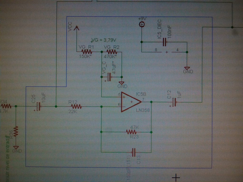
I am reading some material about pcb design and noted what you say is important. But one question about that.
An opamp is used at the output, there one of the inputs comes from a pt2399 delay output and another from a virtual ground. Those two are the traces that need to be of equal length?
Please check attachment
Sorry, I am grasping some new ideas here
I think that doesn't apply because it's an inverting configuration
It doesn't apply because it is not a differential input signal.
the atmega328 should be considered as digital ground, and Lm358 is analogue, right?
Yes. Although the atmega328 has both an analogue ground and a digital one along with two supplies. So if you have any A/D functionality going on then include these on the digital / analogue splits.