Introduction
I am working on a Mechanical Engineering senior design project building a 40lb tank robot driven by a wireless PS2 controller. Following is a basic schematic of the control plan:
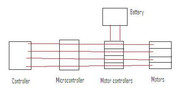
The microcontroller is an Arduino Uno.
The motor contollers are Cytron 10A, 3-25V Single DC Motor Controller (http://www.robotshop.com/ca/cytron-single-dc-motor-controller-2.html)
The motors are standard OEM windshield wiper motors (Monster Guts - Your Wiper Motor / Pneumatics Headquarters!)
The battery is an AGM motorcycle battery (12V, 18AH).
Questions
For Arduino, the base frequency for pins 3, 9, 10, and 11 is [corrected] 490.196078 Hz. The base frequency for pins 5 and 6 is [corrected] 976.5625 Hz. The divisors available on pins 5, 6, 9 and 10 are: 1, 8, 64, 256, and 1024. The divisors available on pins 3 and 11 are: 1, 8, 32, 64,128, 256, and 1024. (Arduino Playground - PwmFrequency)
"The Cytron motor controllers is capable of "speed control PWM frequency up to 10KHz" and "supports both locked-antiphase and sign-magnitude PWM operation."
I need to know:
-
What effect will there be if I output 31250 Hz or 62500 Hz from the Arduino to the Cytron? Will there be overheating or just dropping signals/signal distortion?
-
What effect will there be (on the signal, power usage, etc) of using lower PWM frequencies such as 31250/8 = 3906.25 Hz?
-
What will the effect be on motor performance? Is there tabulated data about the resistance and inductance of these common motors?
-
How do I use locked-antiphase versus sign-magnitude PWM operation using Arduino?
Thank you for your help. Hopefully the answers to these questions don't just make new questions!
John