Here is some info from a reputable supplier Adafruit. NOTE this sensor is NO longer stocked.
That is why their products are a bit more expensive. You get what you pay for.
Looking at the sensor you posted an Amazon link for, the picture looks like there may be a 5V to 3.3V voltage regulator. If you use a lit magnifying glass see if you can read the 3 legged devices near the I2C pins (SCL, SDA)
I mean, I'm retroactively nervous because of your wording here, but in my searching I found numerous articles from different sources. Based on how you said that, my presumption is you're going to dismiss them as not being reputable. But my bruised pride aside, some examples I was following:
Pausing for supper/evening plans. Might have to dive back in tomorrow.
Keep in mind that sellers on Amazon, eBay, etc. often pass off junk, recycled or counterfeit parts.
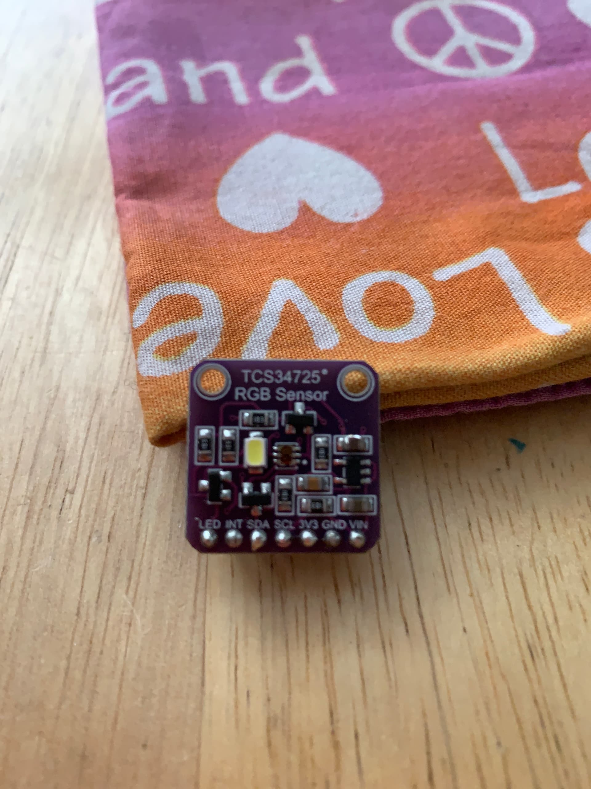
Those are both Adafruit sensors. Yours is not. Take a photo of the sensor as full frame as possible without getting blurry.
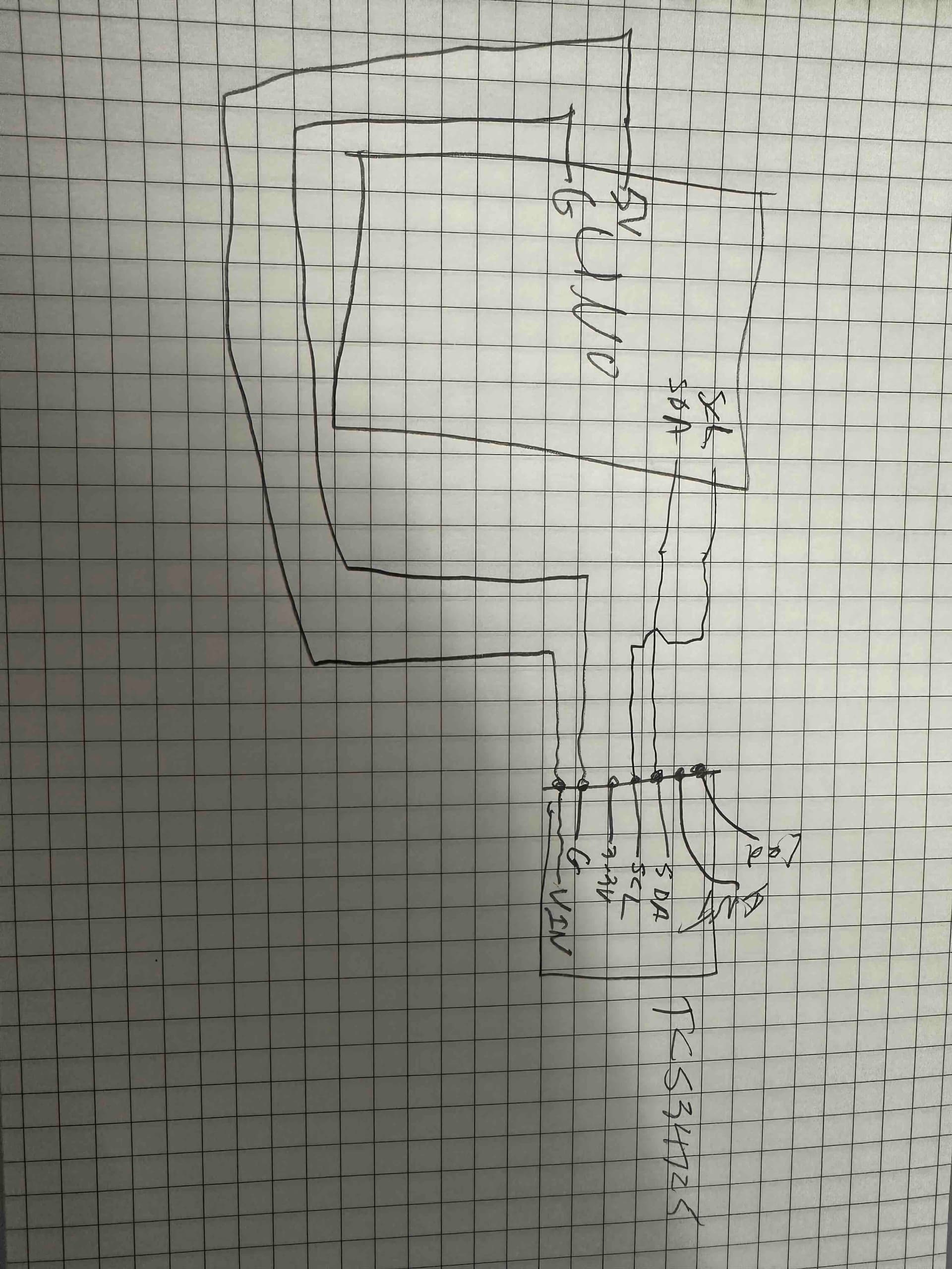
OK, just snapped these pics.
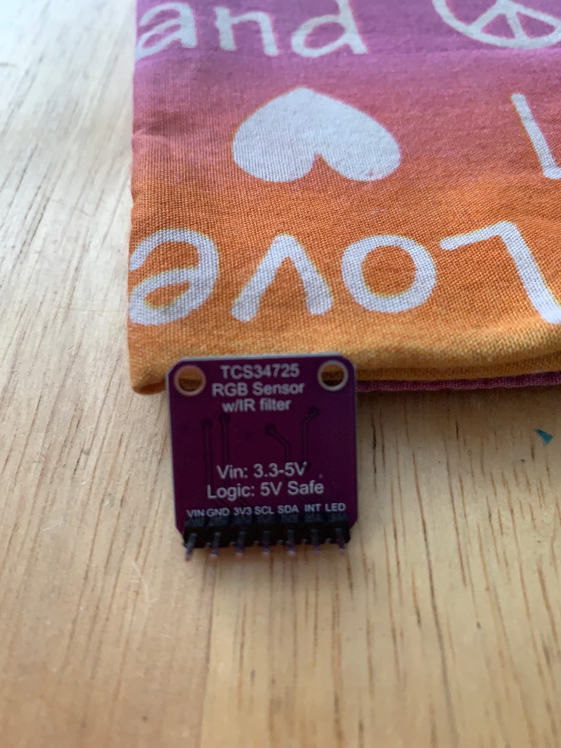
I would like to note in my own defense that if you look at the pic of the back of the chip, the printing explicitly states both that the Vin connection takes 3.3-5V, and also the Logic connections are "5V Safe". I'm not doubting that the general assertion of the chip being fried are accurate, but the chip itself purports to be capable of handling 5V all around. If that's wrong, it's not just digital documentation or a third-party website or even my assumptions, it's literally printed on the chip itself. Would this indicate more just a knockoff chip quality over an actual error on my part with connections?
Anyway, I still appreciate the assistance in trying to nail this down, frustrations at the oddities we're uncovering aside. I initially hesitated to solder more of the header pins onto the remaining sensors I have, in case the problem had been my soldering job. Now I feel like it wouldn't be bad to go ahead and solder on the pins, but I definitely still
hesitate to wire up any further of them before we have some closure on this issue.
I am a bit confused, however, about how to even approach getting a more "reputable" name-brand sensor if Adafruit no longer sells them. Bearing in mind this is inexperience and not laziness speaking, is there anywhere beyond Amazon that would be more appropriate to purchase something like this from? Believe me, I'm all for giving money to someone besides Amazon.
I suspect that sensor is ok. The problem is the datasheets I and others are highlighting are correct in that the sensor is 3.3V BUT BUT BUT if you look at the 'board' you will see a black chip with 3 silver legs, 2 on 1 edge 1 on the other. I will make a medium wager that is a VOLTAGE REGULATOR that take in 5VDC and puts out 3VDC or 3.3VDC
There are 3 chips like that on the board, one above the LED pin, one above the SDA pin and one up top by the word Sensor.
If you can look at the 2 chips near the SDA pin and get the part number it would confirm my hunch.
Now my hunch as I am not trained and am an 83yo autistic person but how does the VR work with a 3.3VDC board? Normally the input Voltage needs to be a volt ot two above the output. I think I saw in the datasheets that the output only needs to be 1.8VDC so that would explain the 5 or 3 statement.
I would accept your hunches over mine (and hey, autistic solidarity - me too!), but I only own an Uno and a Nano. I don't own any other microprocessors with which to test this hunch of yours. Is there any way to adapt the boards I do have or would your advice be to find a purchase a different microprocessor that only outputs 3.3VDC? And if so, any specific recommendations?
If you can look at the 2 chips near the SDA pin and get the part number it would confirm my hunch.
I did my best with my illuminated magnifier, but those are tiiiiiiiny and my 42-year-old eyes couldn't make out much more than scratches. My brain kept wanting to say it looked like "Rin" but that wouldn't make sense, so I'm guessing it's just too tiny for me to see without maybe busting out my DSLR with a macro lens.
Here is what worries me. This chart shows a TCS34727 as using 1.8VDC while the TCS34725 uses VDD which is probably 3VDC or 3.3VDC it will NOT be 5VDC. I am confused by this information.
I am even more confused. I hope we can make some sense of it.
As far as I can tell, it was Adafruit that added the 5V to 3.3V VR on their board. I doubt the native part has that.
I am pretty much convinced you did not toast the board, and also sure that we understand how the 5V vs 3.3V is being done.
So we are back at step 1.
Did you try swapping the SCL and SDA wires?
I'm glad you think the chip might be salvageable after all - I did get a couple of spares just in case, but rather not have to throw any out.
Less glad to hear "back at step 1", of course...
I did not swap them, no, and now I wish I had brought my Arduino stuff with me to work today, but I did not, so I'll have to wait for either tonight or tomorrow to test that. Apologies for the sluggish pace of working through this, I just have my primary workspace at home (despite this being a project ultimately for work), and I don't always bring my Arduino stuff with me if I don't foresee having anything to work on.
I'll give the wire-swap a go at my next opportunity! Thanks for your patience!
All the best, but now that I know this is a work project, I have to drop out.
I mean...I did literally say up in Post #8 above:
This is a project for my job and I was starting out with a cost-savings mindset.
It's been some days since then so maybe it got lost in the shuffle but I want to be clear that I was upfront that this is a project I'm undertaking for work. It's not like matters of copyright or IP or anything, though, I work for an escape room and this represents my first attempt at building a puzzle. It's not sensitive material, is my point.
I don't see any mention of job in post 8.
It's simple really, if you are being paid and I am doing the work then I have a big problem with that.
Good luck.
It's in there, but it's hidden by being conflated with a quote from another user. Easy to miss; I did.
Yes, now I see it. I really do not understand why these people think they can get someone else to do their job. It's such a foreign concept to me and my generation, but apparently not to others.
I'm sorry, it wasn't ever my intention to mislead anyone about this. FWIW, I personally also didn't intend it to come off like asking anyone else to "do the work". My perspective was that this was like a tech support assist. I'm trying to self-educate where I can. I just also learn better by working with someone than reading textbook-style.
But I definitely respect the stance and I don't want you to feel uncomfortable helping me. And for what it may matter, I edited post 8 to separate out the quote from my response. Chalk that up to my first post in this forum - still adjusting to the editor.