Thermistor output changes with voltage

I am trying to output the temperature from 2 thermistors with smoothing. I am using an arduino uno with a 10K thermistor (SEMITEC 103AT) with a 10k resistor. I have 2 problems with my code right now

  1. When connected to 5V as reference I am getting 23.5C (room is probably 21C) connected to 3.3V I get 6C I don't know how this is possible.
  2. If I have a thermistor only connected to A0 the serial output associated with the pin A1 will change as well although it will be a lower number. I have tried adding serial outputs to try to understand where my problem is but I'm stumped.

#include <math.h>

const int numReadings = 5; // number of cacluations used for smoothing
int readings[numReadings]; // the readings from the analog input
int index = 0; // the index of the current reading
int total = 0;
int average = 0; // the running total
int average1 = 0; // the average
int average2 = 0;

#define ThermistorPIN0 0 // Analog Pin 0
#define ThermistorPIN1 1 // Analog Pin 1

float vcc = 4.91; // only used for display purposes, if used
// set to the measured Vcc.
float pad = 9950; // balance/pad resistor value, set this to
// the measured resistance of your pad resistor
float thermr = 10000; // thermistor nominal resistance

float A = 0.8880739089e-3 ; // values from thermistor SEMITEC 103AT SRS Thermistor Calculator
float B = 2.514251712e-4 ;
float C = 1.922794488e-7 ;

float Thermistor(int analog) {
long Resistance;
float Temp; // Dual-Purpose variable to save space.

Resistance=pad*((1024.0 / analog) - 1);
Temp = log(Resistance); // Saving the Log(resistance) so not to calculate it 4 times later
Temp = 1 / (A + (B * Temp) + (C * Temp * Temp * Temp));
Temp = Temp - 273.15; // Convert Kelvin to Celsius

return Temp; // Return the Temperature
}

void setup() {
Serial.begin(115200);
for (int thisReading = 0; thisReading < numReadings; thisReading++) // initialize all the readings to 0:
readings[thisReading] = 0;
}

void loop() {
// subtract the last reading:
do
{ // total= total - readings[index];
// read from the sensor:
readings[index] = analogRead(ThermistorPIN0);
// add the reading to the total:
total= total + readings[index];
// advance to the next position in the array:
index = index + 1;
Serial.print("Total: ");
Serial.print(total,1);
Serial.println("");
Serial.print("index: ");
Serial.print(index,1);
// if we're at the end of the array...
} while (index < numReadings) ;
// calculate the average:
average = total / numReadings;
float temp1=Thermistor(average); // read ADC and convert it to Celsius
index = 0;
total = 0;
readings[0]=0;

// ------------------------------------------------
// second sensor
do{
// { total= total - readings[index];
readings[index] = analogRead(ThermistorPIN1);
total= total + readings[index];
index = index + 1;
Serial.print("Total2 : ");
Serial.print(total,1);
Serial.println("");
Serial.print("index2 : ");
Serial.print(index,1);
} while (index < numReadings) ;
average2 = total / numReadings;

float temp2=Thermistor(average2); // read ADC and convert it to Celsius
index = 0;
total = 0;
readings[0]=0;

Serial.print("Temp #1 deg C: ");
Serial.print(temp1,1); // display Celsius
Serial.print("Temp #2 deg C: ");
Serial.print(temp2,1); // display Celsius
Serial.println("");
delay(1000); // Delay a bit...
}
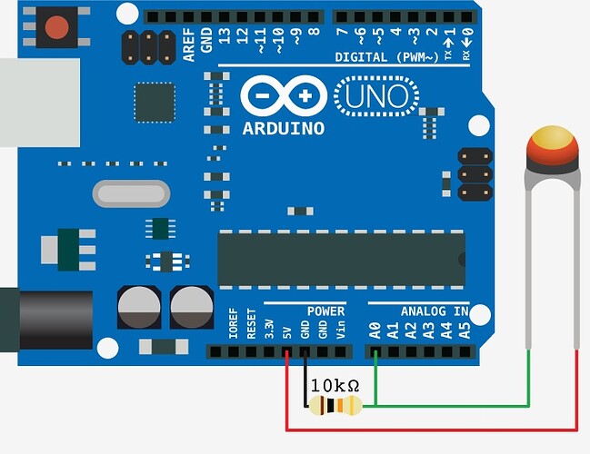
What are you connecting to 3.3V?

The thermistor and resistor act as a variable voltage divider, so if you supply it with 3.3V instead of 5V, I would expect it to read low.

Are you also switching the Arduino to 3.3V? Using Vcc as a reference voltage, or the internal reference?

I'm powering the Arduino by USB and I was trying to reduce noise by connecting the reference voltage of the thermistor voltage divider circuit to the 3.3V pin rather than 5V. So ya it does make sense that the voltage would change as proportionally to the reference voltage.

I was looking at this site Using a Thermistor | Thermistor | Adafruit Learning System where it says:

ADC value = R / (R + 10K) * Vcc * 1023 / Vcc
What is nice is that if you notice, the Vcc value cancels out!
ADC value = R / (R + 10K) * 1023
It doesn't matter what voltage you're running under. Handy!

which is confusing to me. How in the code do I link the analog input to the 3.3V reference rather than 5v reference?

You set the reference to external, then connect Aref to 3.3V.

analogReference()

Description

Configures the reference voltage used for analog input (i.e. the value used as the top of the input range). The options are:

DEFAULT: the default analog reference of 5 volts (on 5V Arduino boards) or 3.3 volts (on 3.3V Arduino boards)
INTERNAL: an built-in reference, equal to 1.1 volts on the ATmega168 or ATmega328 and 2.56 volts on the ATmega8 (not available on the Arduino Mega)
INTERNAL1V1: a built-in 1.1V reference (Arduino Mega only)
INTERNAL2V56: a built-in 2.56V reference (Arduino Mega only)
EXTERNAL: the voltage applied to the AREF pin (0 to 5V only) is used as the reference.
Syntax

analogReference(type)

Parameters

type: which type of reference to use (DEFAULT, INTERNAL, INTERNAL1V1, INTERNAL2V56, or EXTERNAL).

That formula works only if both the thermistor circuit and Aref are running from the same voltage.

Don't forget to add a bypass capacitor to Aref and AVcc. Something like 0.1uF and 47uF.

Do NOT try to connect AVcc to 3.3V. It must run from whatever Vcc for the AVR is.

From the datasheet:
"The ADC has a separate analog supply voltage pin, AVCC. AVCC must not differ more than ±0.3V from VCC."
"The ADC converts an analog input voltage to a 10-bit digital value through successive approximation. The minimum value represents GND and the maximum value represents the voltage on the AREF pin minus 1 LSB.
Optionally, AVCC or an internal 1.1V reference voltage may be connected to the AREF pin by writing to the REFSn bits in the ADMUX Register. The internal voltage reference may thus be decoupled by an external capacitor at the AREF pin to improve noise immunity."

See Figure 24-1. The reference voltage may be Avcc or 1.1V, or the voltage on the Aref pin.
If the Aref pin is not being driven externally, then whichever is selected of Avcc or 1.1V will be present on the Aref pin, hence the suggestion to have a 0.1uF cap on the pin for improved noise immunity.
The analog reading thus represents your voltage divider reading with 1 bit = Aref/1023
With Avcc = 5V, 1 bit = 5/1023 = ~4.887mV
With internal 1.1V, 1 bit = 1.1/1023 = ~1.075mV
With Aref driven externally, 1 bit = Aref/1023.

Here you can see how the ADC reference voltage gets selected, and why it appears on the Aref pin - and why the Aref pin should not be connected to 5V; only a cap to Gnd should be connected.

When using an external reference on Aref, such as the 3.3V available on the Arduino, I think I'd use something like a 1k resistor between 3.3V and Aref, with the 0.1uF (and possibly a 47uF cap) from Aref to ground.

In that way, when the Arduino first powers up and the code has not set Aref to External, you won't be cross connecting Vcc of 5V with 3.3V via Aref.

Also - the internal 1.1V reference is very stable, but it is -not- very accurate. When you use it, you need to take that into account and calibrate for different Arduinos, or if you change the AVR on the Arduino for some reason.

polymorph:
That formula works only if both the thermistor circuit and Aref are running from the same voltage.

Don't forget to add a bypass capacitor to Aref and AVcc. Something like 0.1uF and 47uF.

Do NOT try to connect AVcc to 3.3V. It must run from whatever Vcc for the AVR is.

Thanks for the help Crossroads and Polymorph. When you say do not try to connect AVCC to 3.3V. What do you mean. Isn't AVCC internal to the board?

I have decided to add another sensor in the mix a MPXV7007GP pressure sensor that needs 5 volts. So I need to continue to use 5volts as my VREF. So I will connect a single 0.1uF cap from AREF to ground. Should I also have capacitors on the specific thermistors or is that overkill? The MPXV7007 data sheet has a suggested cap setup so I will follow those instructions.

cap setup mpxv7007.jpg

Yes, use the sensor datasheet recommendation as to those capacitors.

AVcc is connected to Vcc by PCB traces. I was just making sure that, while connecting ARef to an external reference, you did not think that you were also supposed to supply it to AVcc.

The Arduino team kind of fell down when it comes to the analog input sections. As per Atmel's recommendations, a small R should be between Vcc and AVcc, with a bypass capacitor right from AVcc to ground. My Freeduino even has a spot for an SMD capacitor on the bottom, unpopulated. You can at least add a 0.1uF bypass capacitor from AVcc on the header pin to ground.