So if the flat pin head is directly touching the metal on the MAX6675 which is then connected to ground on the Arduino this is bad?
The thermocouple effect is because of the reaction between dissimilar metals. Every change in material is another thermocouple. Use the right materials and connectors or you'll NEVER get reliable readings. Do it right.
I never tried it but if your thermocouple is just floating is for example free air and your thermocouple sheath is not in contact with anything it should not be a problem. If your TC sheath is in contact with anything like a ground then you have problems. According to your link you have a grounded TC. Here are a few of the differences:

So your actual TC junction is connected to the sheath as seen on the left.
Much of this would go better if you explained your full project in detail like exactly what your objective is.
Ron
On page 5 under “Open Thermocouple”.
It seems like it may not need to be if you are willing to give up the open thermocouple detection.
If you can assure isolation of the thermocouple sheath and any part of the circuit you are building I wouldn’t think the grounded sheath would matter. Otherwise I think you could cut the link between pin 2 of the MAX6675 and circuit ground you will be okay. Just no open T/C detection functionality. If I am wrong it might cost you a $15 module or you might just get bad readings.
Have you looked for a similar T/C with no grounded sheath?
By the way, it looks like you could remove the plug from your thermocouple and directly connect the wires thus exposed directly to your converter board.
Just to make comparisons easier:
Your T/C;
My find:
I found this. Perhaps you could negotiate an exchange for what you have. Problem solved.
Hint for the future: put your embedded links on a separate line to get a nic preview block as above.
So your thermocouple is only kinda of grounded. It means the thermocouple junction is connected to the metal sheath. So although not ideal, if the metal sheath is not connected to anything conductive you should be good.
For the below description we'll assume the thermocouple voltage is so low we can consider both input leads to the Max6675 are at the same voltage. The Max6675 datasheet doesn't specify how much the input leads can be related to the Max6675 ground but its probably they are limited to somewhere between 0.5V and 2.8 V (3.3 - 0.5V). So keep that in mind when you build your device.
Thermocouples are not all that accurate, and the Max6675 does NOT compensate for any non-linearities in the T/C transfer function. The Function is will known and you will probably be OK over a limited temperature range.
Which part is the "flat pin head"?
The male pins on the plug have a rectangular cross section but they are quite thin in one dimension so they look flat. Two different widths so it is difficult but not impossible to force them together in the wrong polarity.
Here is a picture of my current set up. There is a copper sphere that has been soldered to the end of the thermocouple (the copper has partially oxidized) to absorb solar radiation. I'll be able to install a new sphere later but for preliminary data taking (since this set up was given to me like this) the temperature is about 5-6 degrees celsius off. So I'm wondering if this is normal or if this is due to the whole grounding issue (it seems like if there was a ground loop I would just be reading 0) or just because the tip of the sheath was exposed to a flame when soldering. If I'm getting somewhat reasonable data am I in the clear?

In doing so, you have created more voltage generating junctions that may add or may subtract from the original junction.
Not unless he penetrated the sheath of the T/C. The copper ball is not affecting the measurement (in the electrical sense anyway). Even if it contacted the T/C junction it would have little to no effect on the measurement since all junctions would be at the temperature and the junction pairs would cancel each other.
I do question the validity of the copper ball though since all it does is add thermal mass and slow down the response time of the T/C.
5-6 degrees of error is not surprising given the sum of the errors of the T/C, the converter and the error budget of whatever you are using as a reference measurement.
1 Like
The only method to solder copper to stainless steel is silver soldering with a torch. I looked at the temperatures for silver soldering and they range from 655C to 780C.
What is the temperature limit for his thermocouple before it is permanently damaged?
So I would suggest you test the thermocouple:
- Boiling water
- Crushed ice in water
Type K is usually good for 1600+ Deg C. How did you connect the copper to the sheath?
And I would be concerned about the insulation on the wires, as well.
Yeah, I wouldn’t have done that myself. If I recall the max temperature for that device is 1200 degrees C. 304 stainless. I suppose one could goober on some solder with an iron and simulate a good bond.
I've soldered Type K wire with an soldering iron at about 400°C . I used a product called "Solder-It", a silver bearing soldering paste. Don't know about stainless.
I've tested a Max31855 K and an Omega Type K T/C. The error was < 1 °C at zero and boiling. Could be slightly more (or less) as I doubt my boiling was exactly 100°C and the ice bath is close but usually slightly above 0°C.
Failure Mode? I would guess since the T/C is still functional that the only issue could be the wire insulation (if a cheap T/C) might breakdown and create more than the single junction.
Nice setup.
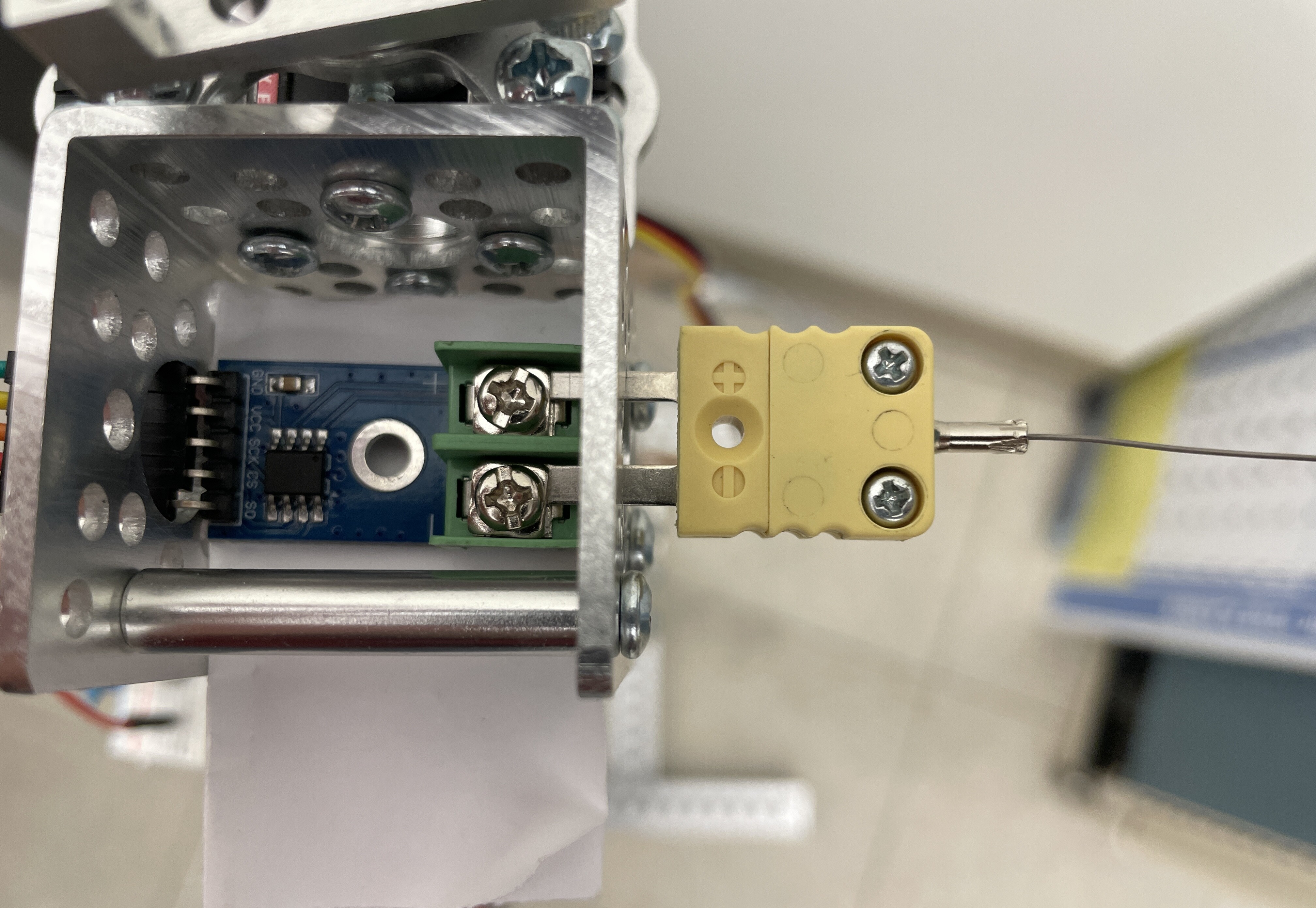
If you find the MAX6674 is at fault I would recommend you get a board like this:
It has better input filtering. See the black SMD device below the 2nd "L" in yellow. Those are inductors to help input filtering. Not every board has them.
There is also an upgrade to the Max31855 (not sure but I think it's Max31866) which would be even better.
Remove the connector shell and wire direct (without solder of any type), OR, buy the mating half of the connector and wire that in.
As built, it may be functional, but the hardware makes a promise (removable connector) that it cannot keep (hard wired, non-removable). Someone, seeing 1/2 of a connector, WILL pull on it until it comes apart, and then will be unable to reconnect.
It may be electrically functional, but it sure ain't ISO9000! LOL
This topic was automatically closed 180 days after the last reply. New replies are no longer allowed.