I too cannot believe this really work. Since the circuit is Arduino pin -> 2k2 resistor -> gate -> source -> 10k resistor -> Arduino gnd there is ~12k resistance in the current path when (dis)charging ~20nC of gate capacitance. Since most of the gate capacitance is ~5V (see Fig 6 here) I think we can estimate charging current will be less than 1V/10k = 100uA and so time the MOSFET stays in linear region when switching on is more than 20nC/100uA = 0.2 ms! Since default PWM frequency of pin 6 is nearly 1kHz the poor MOSFET is more than 1/5 of time in linear region if I am right. And probably even more...
Data sheet lists Qgs = 9 nC, but this are three MOSFETs so total required charge would be 27 nC with effective resistance of just over 10k. Seems you may be optimistic here, but calculations are a bit more complicated thanks to those resistors and a minimum Rds(th) that has to be reached first.
I missed that the 10k also limits this charge/discharge cycle, I only looked at the 2k2 resistors between Arduino and the MOSFET gates.
OP probably didn't put a serious load on it yet, and/or doesn't realise his duty cycles are lower than they should be (though they most likely do indeed follow the NTC). With just 1-2A total it may indeed just work.
Yes right i did not put a full load of 30 Amp Yet, infact one Heavy DC motor of i guess 10Amp runs fine, and resistors are just to prevent Arduino from frying. Diods/ Caps dont work for this purpose. Mosfets remained cold because the fan that i was running with this PWM was pointed at them.
Besides "I dont know a dime" about the calculations you guys are doing. thanks for your help, I told you before I am a noob in this field ( arduino, Coding, Electronics) this is my 3 days of learning + practical demonstration.
So far I have learned to modify codes, get display on serial monitor, temperature festivity of these glass thermistors is oout class, finger at mare 2-3mm distance can transfer heat and kick MOSFETs which run fans.
My new query is LCD display, how to convert Thermistor circuit reading at A0....( range from 480-610 ambient temperature) into celcius. Then i shall be displaying this along with Voltage and Ameter on my LCD/Serial.
I appreciate your help guys.
Heat production increases squared with current. So 3x the current (for your 30A load, assuming you're correct with your guess of 10A for this motor - do check it's specs - I doubt it's that much or you'd notice significant heat) means 9x the heat.
For the other calculations: do start learning, and make sure you understand what's going on, including why those resistors you add to "prevent frying the Arduino" (what makes you think this is the case?) may very well be part of the cause stuff starts frying.
You're dealing with some serious currents here and the specs of your MOSFETs mean they can NOT handle it properly (you seem to simply ignore that part - which doesn't matter, because sooner or later they'll simply blow and you have to look for replacements, just make sure you don't hurt anyone in the process).
Hi,
Use 220R instead of 2k2.
Reposition the power relay on the battery to switch battery positive.
Fit a fuse to the motor power circuit.
Change the colours in your diagram, RED is POSITIVE power, BLACK or BLUE is NEGATIVE/GND.
Some indicator lights to show power is applied would be advisable.
Can you post a picture of your project so we ca see your component layout?
Thanks.. Tom.. ![]()
Hi all,
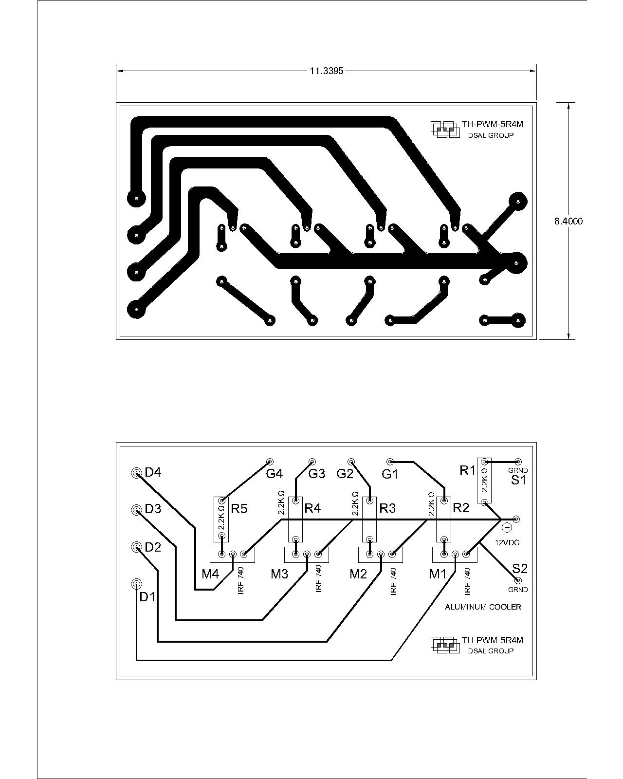
Loads of work ( my Architecture practice) and finally i got free on this Sunday to work on my Thermistor Controlled PWM project for 12 VDC I am calling it " TCP-01" , so produced a pcb using this drawing for the above concept. this drawing i produced on AUTOCAD which i use for my Archi projects.
Hope you get an idea. PCB is ready with etching and all components installed. I am about to test it real time, may take a few days, because i am going to be busy again.
pcb circuit pwm hho.pdf (65.8 KB)


Hi,
What does R1 do?
What is S1 and S2?
Can you please post a copy of your complete circuit, in CAD or a picture of a hand drawn circuit in jpg, png?
Showing all your connections and labels.
If you can do PCB layout, you can do a decent schematic...
Thanks.. Tom.. ![]()
Isn't it wonderful how all our good advice is completely ignored?
No flyback diodes. No pull-down resistors on the gate. Still an improper MOSFET. No obvious space for a 60W heat sink.
TomGeorge:
Hi,
What does R1 do?
What is S1 and S2?Can you please post a copy of your complete circuit, in CAD or a picture of a hand drawn circuit in jpg, png?
Showing all your connections and labels.
If you can do PCB layout, you can do a decent schematic...
Thanks.. Tom..
R1, R2, R3, R4, R5 is for controlled voltage of signal to MSFET ( safety for arduino)
G1 and G2 is analogue singal coming from Thermistor
( 5v----thermistor(10K)----A0----resistor(10K)---GND) typical Signal A0, or for A1 etc
I am an architect and it is the progress i made in just 4 days of learning and experience, So, dont expect a master piece yet. S1 is for GND signal for Arduino and S2 is i kept to measure Voltage / Amperage etc for future
sdaniraza:
Photos of the project, planning to add a large aluminum heat sink for these MOSFs....
photos
How do you post photos in text?????