"Tiny RTC I2C Module" issue

I have 4 of these DS1307 modules. Only one was working correctly, and I noticed that it has no resistor R7, where two of the modules do have an R7 resistor. After some googling I found that R7 connects to the crystal and this is not recommended. So I fired up the soldering iron and removed this super tiny resistor from the two modules that had it. These two modules will now increment the time when not connected to 5V power, where before they would 'freeze' the time to what it was when the power was removed. My other module has a short on it somewhere, but is hardly worth the effort to track it down. I've spent too much troubleshooting these modules already.

If you look closely at the DS1307 modules on eBay, most of the newer modules will have R7 removed. (It is usually placed parallel to the Vcc/Gnd connection near the edge of the board.) That whole design for the DS1307 modules seems to be overkill to make them work with rechargeable batteries. The DS1307 should work for years with a non-rechargeable coin cell, and with a minimum of external components, without this added recharge circuit.

The DS3231 modules on ebay have dropped in price dramatically, and they are much more accurate and software compatible with the DS1307 code. But these are obviously cloned chips at these prices, so caveat emptor.

-transfinite

I couldn't get this thing to work. I'm for sure not buying another one of these, cheap but useless...

It could be user abuse. I have a few and, while not that accurate, they all work fine. The 3231 is more accurate and hardly any more expensive these days, but the latter may mean it is no more reliable. The one I have is notably more cumbersome, which is something you might need to bare in mind.

Maybe you are right and I'm judging in just one single experience. I'll maybe order another one to try it out, they are ridiculously cheap anyway. Its a pain having to modify the board to use with a non rechargable cell tho.

My troobles with this module:

  1. time stop when Vcc disconnected. When Vcc connected - time goes slowly. One minute of RTC time like 3 or 4 real time.
    SOLUTION: Problem was in crystal oscillator - it case was loose from its solder pad.
  2. Some times, module time becomes not real - like "2165/165/165 165:165:85".
    SOLUTION: I found, that it happens when I solder the module without Vcc disconnection. You have to disconnect Vcc, remove the battery and wait one-two minutes. Of course you must set time again after that.

I use a 1307 which I bought as a chip, not a module. Reputable local supplier so I assume it's genuine. I already had the crystal (of correct capacitance, not just correct frequency). No problems at all, set up on breadboard with a coin cell backup.

I use the DS1307RTC library.

(I originally thought its timekeeping was poor, but I think that was my finger trouble and eyeball co-ordination between the RTC output and the computer clock.)

8bit_pawel:
Hello everyone with Tiny RTC problems,
I was experiencing them as well, but, at least in my particular case, they appear to be solved.
Problem description:

  1. Something like this:
    RTC is NOT running!
    2165/165/165 165:165:85
    since midnight 1/1/1970 = 1381621585s = 15990d
    now + 7d + 30s: 2013/10/19 23:46:55

Sorry for big quote.

Way back when I was learning and trying to get my alarm clock working, I had similar problems with the funny readings from the RTC.
For me it turned out to be a bad I2C connection rather than anything else.

I can't say more but it had me going nuts for a week or so.

Oh, and in case anyone else is also stuck on setting the time.....

Something else which had me going nuts when trying to do that:

I would set the times in the program and then hope/think/believe that somehow the RTC was set.

Nah! You have to set the times in the program (and how you do that is dependant on the program/sketch) and STOP the clock, SAVE the time then RESTART the clock.

Otherwise it won't work.

That too had me stumped for a while.

Hi Guys.
I landed here whilst looking for something else.
This is my first post here. I'm a PICer not an Arduinoite, and just a fumbling trial by error hobbyist pining for the days of hot valve burns and HT shocks.

I too was having issues with the Tiny RTC and after months of testing and research made a very interesting discovery. I thought I would share my findings:

If you want to skip my diagnosis background and just read the solution that worked for me, jump to the "=========" below. (I tend to go on a bit)

I had around 10 of these modules, a mix of v1 (blue PCB) and V1.1 (white PCB) from 4 sources, 1 UK, 2 China and 1 Hong Kong, but NONE directly from DFRobot. 8 of them were misbehaving but not all were the exhibiting the same symptoms. I can't be sure where I got the 2 good ones from, as they all got mixed up before I realised something was amiss.

  • 8 of the 10 of the modules tended to run fast by between 5 and 90 seconds per day.
  • 2 of the blue type 1 modules worked as expected.
  • Some would not power down reset back to weekday0, 01/Jan/00 00:00:00 clock not started. and would display arbitrary and sometimes invalid dates and times. I can't remember exact values, but dates like 35/14/87 02:68:03. (UK format)
  • The inconsistency in faults applied to both blue and white types.
  • Some would cold "start" without a write instruction and others would not.

I have an old dual trace scope, but no frequency counter. I removed the electronic module from a cheap wall clock that has always kept good time and Through a 1 meg resistor and a X10 probe (an attempt to minimise the impedance effect of the scope input) I got a good trace between the PCB ground plane and one side of the crystal. I set the RTC module SQ out to 32768 HZ and compared the traces, and sure enough, the modules were running faster than the clock, and the differences between traces for different modules corresponded to the time keeping data I had collected.

I got lots of suggestions from other forums and tried adding DC decoupling capacitors, different PSUs, batteries, high accuracy crystals and adding RFI shieldingin desperation I even tried adding variable load capacitors between the Xtal pins and +ve rail to slow down the frequency. This had limited success in that timekeeping improved during the short test duration, but I suspect it will cause instability and reliability issues over longer times.
Swapping crystals between a 'good' module and a 'fast' module made no appreciable difference in either module's performance. Neither did swapping crystals between blue and white modules.

I contacted two of my suppliers who both said the same thing : Send them back to China (recorded delivery 32 UKP) and if they agreed they were defective they would replace them. They were clearly box shifters and would unlikely have the time or the gear to test them and the round trip would be up to 180 days. I'd changed crystals and hacked them around by now anyhow.

I contacted DFRobot (manufacturer) support and got a quick response. After getting past the initial "Have you plugged it in?" "there must be something wrong with your circuit/micro controller" suggestions, we entered in a lengthy diagnosis of several subsequent email exchanges, which involved videos and macro photos of the boards. DFRobot concluded that they couldn't replicate my issues although the photos I sent "appear" to be their own modules, but could not confirm unless I sent them to them. They couldn't honour any guarantee as I didn't buy from them (fair enough). Neither would they send me a sample, but they did suggest I could buy more direct from them. I was surprised at this response as I would have thought that for the sake of a few dollars they would want to get to the bottom of this and would want at least my 'free' test data and findings if not my silence. I had already bought 10 and I wasn't about to buy another 8 modules on a wing and a prayer until I was satisfied the problem was solved. They didn't seem to agree with my logic.

I then contacted Maxim tech support. Again, many email exchanges trials and videos later it transpired that DS1703 chips on 2 modules had die stamp manufacture date & batch code numbers that matched Maxim's records and the other 8 modules didn't. It is interesting to note that up to this point I had not told Maxim that 2 of the modules worked fine, and these two modules had the chip codes that they recognised as their own.

=======
So, as I see it, according to Maxim it appears that 8 of the 10 Tiny RTC modules I had purchased appear to have been manufactured using counterfeit chips and when these chips are replaced the module works very satisfactorily. I still don't know if or how many of the modules I bought are genuine. If they are, as DFrobot tells me they appear to be, then 8 of the 10 have been manufactured using chips that Maxim don't recognise as their own. I have conveyed Maxim's comments back to DFRobot. I am surprised that DFRobot have not yet replied. There is always the possibility that I have misunderstood something that was said, and I am not suggesting that DFRobot are using counterfeit chips, knowingly or otherwise, and it is quite understandable that DFRobot has no control of un-reputable companies copying and selling their products. If they do get back to me in the coming months, I will post an update.

I bought a roll of DS1307 chips from what I believe to be a reputable mainstream supplier and replaced the suspect chips on the 8 modules. ALL the issues have disappeared and all 8 now work as the other two and keep good time. I haven't checked the die stamp codes on these replacement chips with Maxim, but have no reason or evidence to suspect they are not genuine.

In reply to someone-else's post, none of the through-hole mount crystals had their can soldered to ground on the 4 blue boards and all of the surface mount crystal cans (in plastic holders) were soldered on the 6 white boards as part of their mounting.

I post this in good faith and hope it helps someone. I apologise if my ramblings have not come across as I had intended. I'm a grumpy old duffer, and it wouldn't be the first time I was accused of being over opinionated git. :slight_smile:

BTW If anyone knows if there are any safety issues in the way the LiR2032 3.6V battery is charged on these, I would love to hear them.

Hi to everyone, i'm new to the forum, i've planned to take part of it but now i have a reason to do so. :slight_smile:
My experience with the tiny RTC module was quite deluding but right today i've discovered a solvable issue that seems no one has yet discovered and has caused to me a lot "stress".
Problem: I2C sporadically returns bad values or even hangs the entire program.
Solution: LIFT THE BATTERY HOLDER :smiley:
Actually the negative springy plate protrude beneath the plastic with some "pins" and touches a line between SCL or SDA (i didn't investigate) or even both and shorts it to ground causing bad behaviour of the I2C system.
See my photos
tags: i2c iic twi problem issue tiny rtc ds1307 hangs crashes errors at24c32

DSCF4889.JPG

DSCF4886.JPG

update0:
the problem i described in my first post was a reality BUT the I2C missbehaviour remained (this time if i flex the center plate it doesn't hang but hangs later)
update1:
i desoldered the chip from the module and i've discovered a weird goo all around it, not solder residues nor glue for something to hold :confused:
update2:
i installed the chip on a semitemporary monstruosity circuit i made after removing all the goo from it with my fingernails and..... now it works well without I2C problems, goto photo; :confused: :confused:
update3:
i've discovered that the clock goes faster than normal and inacceptably
now i'm trying to find a couple of capacitors i'm connecting between the two cristal pins and gnd (blewtobits said he connected them on vcc but i'm not comfortable with that, many thank to him anyways)
i've tryed 2pF then 3pF then 8pF and this time it looks like it's holding the tempo, maybe the actual problem of this chips are the two input capacitors that are not "big enough", likely theese are counterfait parts

DSCF4891.JPG

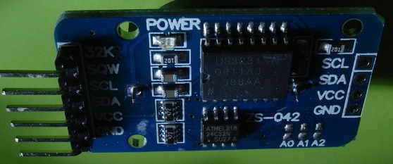
I purchased several of the type of RTC module being discussed - mine have no temp sensor soldered in the corner (at U1), came with an LIR2032 (3.6V Li-Ion rechargeable button cell), and were silkscreened "Tiny RTC I2C modules" (yes, plural). Since I'd ordered them for cheap (US$1.25 each, shipped) and the seller had declared them without batteries, I was quite thrilled not only to have received units with batteries, but to find that they were rechargeable. As already mentioned by others, D1 should be removed if you're using these with conventional (non-rechargeable) CR2032 batteries.

I was thrilled until I went to test an arbitrary one from the batch. I soldered on a 4-pin header (didn't need clock out, battery monitor, or the temp sensor that wasn't present anyway), obtained libraries, and promptly found that I couldn't comm with the device. Got another library, that successfully comm'd - I could read the NVRAM (and if I dumped 256 bytes instead of just 56, I'd also see the stored time values near the end of the block). If I set the time, it'd write to the NVRAM, but the clock would NEVER UPDATE. I removed the battery, checked it and found the voltage was low but rising. I figured there was some sort of short, but there was no low resistances between the battery holder contacts, so I presumed after something was driven powered up, it was latching Vcc to GND or such. With Vcc (no batt) I checked the oscillator using a scope, and found it wasn't running - there was Vcc present, but no oscillation. De-soldered the crystal (which as others have noted, did not have its casing soldered to the immobiliser pad) and replaced it with a 1206 size SMD crystal of the same frequency (I have a binload of SPI RTC units and 32K crystals for other implementations). Still no luck. Note that the case pad has continuity to GND -- it is not merely an island.

In examining the module closer, with the battery removed from its holder, the positive clip (the contact to the side of the battery rather than on the face), had a prong near the base which was too far inwards - such that when the battery was slipped in, that prong would be contacting the face of the battery just inside the "seam". I carefully bent that outwards, inserted the battery, and connected the module to my test rig. Wouldn't you know it, but the oscillator was doing its job, and the RTC would keep time.

That clip issue explains why the battery was shorting out and why the battery was recovering voltage after I removed it from the device. Anyone experiencing an apparent short (esp when not even connected to your project), and not measuring expected battery voltage across the two circa 1.3mm through holes (one between the ICs and the other "above" R6) should check the battery contacts and ensure the side clip isn't bent inwards as mine was.

Note also that some RTC librares in their constructor/initializer set a flag indicating whether they successfully commed with an RTC module. So it you start up and the RTC isn't seen, it'll run an internal RTC implementation (so long as the host AVR is running), and NEVER COMM WITH THE RTC MODULE even if you get it connected properly after that - you'd have to reboot the uC. This was a PITA while dealing with an RTC that wasn't working right, because from all outward appearances, the RTC library WAS working. That made the problem look more like the RTC worked, but wasn't running from battery when the uC reset -- except that I could fully remove the RTC, and the darned library would still be keeping time (which is what clued me into it using an internal fallback for timekeeping). I temporarily instrumented the library code with a few debug statements ("Using realtime" and "Using bogotime") depending upon whether the RTC was actually found, and added the ability to reset the library (moved the initialization code into a reset function, and had the initializer call the reset function) - this because I can't use new or destroy in the crippled bastardization of C++ used in Arduino.

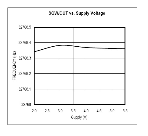
I haven't performed long-term testing of the module just yet (one test would be to read time periodically and waypoint it against the millis() of the uC), but overnight it kept time well enough that I know the module functions.

I subsequently found another seller on Ali Express listing the same module (declared as including the LIR2032 battery) for US$0.95. SHIPPED. I can't buy just the clock chip for that, nevermind the 32Kbit I2C EEPROM (which I have employed directly in circuits before) or the rechargeable battery.

The AT24C32 module functioned just fine (even when the battery contact was a problem, since the flash module doesn't rely on battery) - I could write values say 16 bytes in sequence (i.e. not crossing pages) with the base address being stored into those locations, then come back and read and display the lot and would get the expected result, which confirmed that I had the full 4K byte addressable space and there wasn't addressing wrap. I didn't happen to try to go beyond the stated capacity to force addressing failures. As a side note, because it is a serial EEPROM, you could desolder it and resplace it with a different capacity device if you needed to - or even desolder it from this PCB because you don't need it, and use it in a different project entirely.

Of course, the AVR processors have EEPROM storage as well. If you're scratching your head about what to use the EEPROM for, not that you can store device serialization and calibration data in them - you could "characterize" the RTC against a more reliable time source and write the drift data into the EEPROM (so many sec per day), and tweak the RTC library to automatically shift the clock readings (and store the time of the last correction to the RTC RAM).

Not on this device, but on the AVR projects themselves, I store a unique serial identifier in the EEPROM so that when I send data from the device (usu. via radio), that unique identifier is in there for the receiver to correlate the data to the transmitter device (many to one).

In diagnosing the nature of the device failure, it did not help that there are several for-crap libraries out there, and that some "play" RTC if they don't successfully comm with the device (instead of returning some sort of status).

Note that before isolating and fixing the battery clip, I had run an I2C scan which found the two devices at I2C IDs 0x68 (RTC) and 0x50 (EEPROM).

update0:
both the "speedup" issue and the I2C problem seem to be gone, but hooking up an 1602 I2C LCD (so increasing the overall capacity (but reducing the pullup resistors)) caused bad behaviour of the I2C again (but VERY VERY rarely), the total cable lenght is about 30cm now
the perfect value for the two capacitors to install on the Xtal pins is 9pF each (8pF on X1 and 10pF on X2 in my case)

update1:
i've reduced the pullup resistors to ~1k7 each from ~4k1 (accordingly to online data it's the lower minimum value) (arduino leonardo 20k pullups || 10k || 10k (now + || 3k )) and ANY reading fault seems to be definitively gone!!
(i've arranged a some sort of "checksum" sketch that continuosly check for consistency and the circuit passed the test runned for hours)

update2:
i discovered (trying to find the PPM max error of the DS1307) that the datasheet "states" that there's a 1sec error every day in the "faster" side and no other hints so far for knowing the max PPM error of the IC
goto photo;

i've orderd a pair of DS3231 modules, maybe this time.....

@all of you:
do you really need a library? (maybe in my case i've read the datasheet BEFORE the module arrived to me :wink: )

Immagine.jpg

Look at the picture...

Edit: Don't bother, it won't work anyway.

update0:
now everything works fine
goto picture;

update1:
the DS3231 modules are AWESOME, no I2C errors whatsoever and they keep time with a precision that i've never seen, datasheet says "less than 1 sec every 10 days" and after a week running there's no difference between the (synced) PC clock and it, i've also already tested every function of this IC and it works wonders
i'm including a photo of one of them in case one of you wants to buy one\some of them and want to see how a "good" one looks like, mine were shipped with "CR" batt.s (1.20€ each shipped, if you want to know)
goto otherPicture;
and.... yes, they have a charging circuit as well so you need to desolder the diode (easily doable by lifting it with the iron's tip by a side) if you want to use a "CR" battery, however LiIon batteries cannot be trickle or float charged this wildly, i also got rid of the LED to avoid "heating", BTW the ondie temp. sensor is accurate too, i think it has an error of +-0.5 °C

happy thinkering :smiley:

DSCF0268.JPG

DSCF0267.JPG

i almost forgot...

update2:
i've discovered that...
the Windows time sincing feature has an error of around 1 sec, if the BIOS clock is within 1 sec of error from the server's time it will not be adjusted (even if it says it was) so don't panic if your clock looks like it's shifting one sec in something like half of a day, because the mainboard timekeep is delivered by a 10 MHz crystal that is not accurate like a 32.768 kHz tuning fork one and Windows "cannot" adjust it by less than 1 sec

Thanks all. I think I got my ("Tiny RTC I2C Modules") working. I cut the traces, jumpered the resistor, and soldered the crystal.

Then I had to jump through a bunch of set clock, power off, power back on sequences, until I finally got the time set.

I didn't replace any resistors or capacitors, although I do plan on keeping the I2C jumpers short.

Mine does not have to be very accurate, just within a minute or two.

I almost gave up a few times. These are so cranky. Even if it is not perfect, at least I have something working until I get possession of a better RTC module.

I'm so glad I found this thread before trying to get this module working :slight_smile: thank you to all who have contributed.

I did the mods suggested by RoomHelli (in post #28) and found a way to use the existing R6 as the serial resistor to the BAT pin to reduce the current drawn by the Arduino ADC input pin with no Vcc connected.

Instructions as follows (refer to the attached image "Modified Tiny RTC circuit board.jpg"):

  1. Remove D1, R4 and R5.
  2. Cut the track between R6 and R4 (being careful not to cut adjacent tracks!)
  3. Cut the track that leads to the BAT pin of P1 where it runs under the word "GND" printed on the board adjacent to P1.
  4. Connect a wire between the left pad of where D1 was to the top pad of where R4 was.
  5. Connect a wire between the bottom of R6 and the BAT pin of P1.

To check your mods: measure the resistance between the top of R6 to U2 (the DS1307) pin 3; this should be ~0 Ohms. Also, measure the resistance between the top of R6 to the BAT pin of P1; this should be ~500 kOhms.

Hello!
I’m trying to make Arduino mega, LCD and tiny trc work.
I have found out that shortcut BAT and ground display the right time without the shortcut its display 25:165:85 165/165/165. If I take the battery out its showing the right time as well but on Power down the time will be reset (not good).

But I don’t know if it is good to connect BAT to GND??????? Am I shortcutting the battery?
Is there a working rtc with Arduino mega?

hi,i have a problem with my rtc
my problem is
RTC is NOT running!
2165/165/165 165:165:85
since midnight 1/1/1970 = 1381621585s = 15990d
now + 7d + 30s: 2013/10/19 23:46:55

@both of you
don't use a library, study the datasheet of the ds1307
just remember that the numbers on the DS are stored in "binary-coded decimal" format