Hello,
I just started to learn the Arduino Uno with my student kit. So far so good, except I have some difficulties to be able to read voltage, resistance with the multimeter.
I have very random try, sometimes the measure is stable, sometimes there's a lot of fluctuations. For example, in lesson 3, the one where you build a traffic light with a push button, I am not able to get the voltage who goes through the button, same when I want to measure a resistor.
I checked the multimeter with a voltage battery measurement, it works fine.
So is there any tips, advises, way of doing who could help me to get more solids measures?
Thanks in advance.
Not everyone here will know what lesson three involves, so if you could provide links, and maybe describe in some more detail what and where you're probing, better advice may be simpler to provide.
// traffic lights
//push button will warn cars with a blinking red light than
//pedestrians has the priority to cross the street.


void setup() {
  //declare digitals pin2 to input and pin3, 4 and 5 to output
  pinMode(2, INPUT); //push button
  pinMode(3, OUTPUT); //LED green
  pinMode(4, OUTPUT); //LED orange
  pinMode(5, OUTPUT); //LED red
}

void loop () {                      //loop
  if (digitalRead(2) == LOW) {      //when the push button is not press
    digitalWrite(3, HIGH);          //LED green on
    digitalWrite(4, LOW);           //LED orange off
  digitalWrite(5, LOW);             //LED red off
    delay(5000);                    //wait for 5s
    digitalWrite(3, LOW);           //LED green off
    digitalWrite(4, HIGH);          //LED orange on
    delay(2000);                    //wait for 2s
    digitalWrite(4, LOW);           //LED orange off
    digitalWrite(5, HIGH);          //LED red turn on
    delay(5000);                    //wait for 5s
  digitalWrite(5, LOW);             //LED red turn off
  } else {
    digitalWrite(3, LOW);           //turn off LED green
    digitalWrite(4, LOW);           //turn off LED orange
    digitalWrite(5, LOW);           //turn off LED red
    delay(500);                     //wait half a second
    digitalWrite(5, HIGH);          //turn on LED red
    delay(500);                     //wait half a second
    }
}
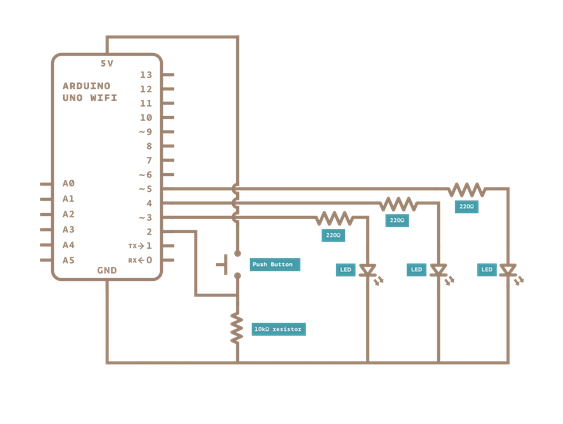
Here's a picture to describe the circuit. As you see on the image, I tryto get the difference of potential between the switch pin 1 and the ground. When the switch is not press, the voltage should be 0 since the resistor is a 10k ohm.
But when the switch is press, I should measure a difference of potential since my second block of code is executed correctly (the one in the else part).
I tried many time to get something on the multimeter (set up the dial on 20V), I only got zero.
To get the measure, I put my test leads as the picture shows, press it firmly, be sure the tip is in contact with the wire.
I succeed in previous exercises to get some measures (voltage, current, resistance), but I feel it s a little sketchy, sometimes it is working, sometimes not. So just wondering if there are some ways I could improve the way I get my measures.
I'm not sure if your meter is actually connected to the circuit... I'm not sure if that group of 5 connections on your breadboard are connected to the other "ground" connections. They might just be connected in groups of 5... You can check that with by checking the resistance (Ohms). And when you measure resistance, make sure power is off.
You may also need to check your switch (with the Ohmmeter) because although there are 4 terminals there are only 2 switch-contacts.
Yes they re all connected to the ground. I checked the resistance and I have around 10K ohms as expected. I also measure the voltage between pin 1 and pin 3 of the switch when it is release, it gives me 5V, which make sense ((pin3 = 5V) - (pin1 = 0V)). Then, when I pressed the switch, it gives me 0 since there's no difference of voltage between the 2 pins.
I couldn't get the voltage with the way described in the image of my previous post , but I assume it's around 5V (pin1 = 5V - ground).
Thanks for your help both of you, it helped me clarify what's going on.