TM1637 using all dot ?

Hi,
Please post a copy of your circuit, a picture of a hand drawn circuit in jpg, png.
Hand drawn and photographed is perfectly acceptable.
Please include ALL hardware, power supplies, component names and pin labels.

Please post your complete code.

Please post some picture of your project, so we can see your component layout.

Thanks.. Tom.. :grinning: :+1: :coffee: :australia:

Thank you ruilviana for your question.

5463BB.
The last B is blue.
The first B is for common anode ( A is for common cathode)

datasheet about 5463BB

All test sketch I tested, worked fine.
All sketch from TM1637-master/example work fine.

Before write mine sketch, I just want a command line awswer to my fisrt post.

I don't need them "all".
Please show any code, that you have tested with your display and it works!

Don't expect a ready-made solution. No one knows exactly what kind of display you have. In order to find the right command, you need to put in the effort yourself - answering questions, running tests when asked... and not just respond "is not good to my question" to any attempt to help you :slight_smile:

I'm absolutely sure that if there are dots on your display - they can be controlled separately from the other segments. But you must help us help you - otherwise you will never find a solution


where is D1 disappear ?

Probably D1 does not exist on that particular display. The plastic housing will often have the positions for the colon and dots, but the actual LED behind those may not be present.

It would be extremely unusual to have the four dots and the colon, there are not enough segments in each digit to control a dot and a colon independently. The TM1637 is capable of controlling six 7-segment displays, so a separate colon could be driven by a "virtual" 5th digit position, but I don't think I've ever heard of a display that did that.

Hi, @iamnotgenius
I Googled;

4 digit led display arduino tm1637

I found this excellent tutorial that if you read through, describes how to control the individul dp's and time colon.

Tom... :grinning: :+1: :coffee: :australia:

Thank you for your answer.
Before coming here, I take a look to many tutorials, I try many sketch to understand how my tm1637 works.
I already readed this link. Autor wrote dot and colon is 1 . 2 : 3 . 4 but mine is 1 . 2 . : 3 . 4 .

I will take a multimeter and test each 5463B pin...
Wait and see !
But In France it is chidren hollidays, I be back few days laters.

Thank you everybody for your answers.

@iamnotgenius
Firstly, I would like to comment that there are several hardware and library versions for this module.

Libraries I managed to identify at least 3 different ones: (or even more).

1." GitHub - Seeed-Studio/Grove_4Digital_Display: Display for digital tube
2." GitHub - avishorp/TM1637: Arduino library for TM1637 (LED Driver)
3." GitHub - maxint-rd/TM16xx: Arduino TM16xx library for LED & KEY and LED Matrix modules based on TM1638, TM1637, TM1640 and similar chips. Simply use print() on 7-segment and use Adafruit GFX on matrix.

Hardware I managed to identify at least 3 different ones: (or even more).

  1. Only two dots between digit 2 and digit 3.
  2. One decimal point for each digit.
  3. One decimal point for each digit and 2 points between digit 2 and digit 3. (I think something is fake).

See the images below.

As my module had a display with only two dots between digit 2 and digit 3, I removed
the original display and I mounted two 2-digit displays with decimal points on a proto board and connected them instead
of the original display. (It wasn't pretty but it was functional).

Then I wrote a code to only light the DP of each digit.
(I know that the code can be optimized, but even though it is not beautiful, it is functional and meets the need).
Follow the code below the video.

In the video below you can see the result of the assembly and code.

Now let's analyze the displays.

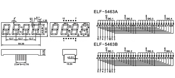
All 3 displays have 12 pins, 1,2,4,5,7,10,11 connected in segments A,B,C,D,E,F,G.(not respectively).
Pins 6,8,9,12 connected to the commons of each digit.

Display n.1. Pin 3 connected to the two points between digit 2 and digit 3.

Display n.2. Pin 3 connected to the DP of each digit.

Display n.3. Pin 3 connected where? connected at the two points between digit 2 and digit 3 or at the DP of each digit?
After all, there are only 12 pins.

With 12 pins it is not possible to connect the 7 segments (7), the 4 commons (4), the DPs (1) and the 2 points (1) separately. (7 + 4 + 1 + 1) = 13.

The datasheets I found are confusing and have gaps in the information on the points.

Ref:

  1. 3642BS DP, Colon between digit 2 and digit 3.
    I couldn't find the data sheet for this type.

  2. 3641BS DP, of each digit.
    "http://www.xlitx.com/datasheet/3641BS.pdf

  3. ELF-5463A-B, DP of each digit and colon between digit 2 and digit 3.????
    "https://www.yitenuo.com/download/4/ELF-5463A-B.pdf

image:

Video:
"I don´t now how upload video. :woozy_face: . I will try later.....
PS: I couldn't upload video.
But it is available at: Imgur: The magic of the Internet

Code:

#include <Arduino.h>
#include <TM1637Display.h>
#define CLK 2                                     // To TM1637 Clock pin
#define DIO 3                                     // To TM1637 DIO pin
#define TEST_DELAY   500                          // delay for each display
TM1637Display display(CLK, DIO);                  // TM1637 instance
//--------------------------------------------------------------------------
void setup() {
}
//--------------------------------------------------------------------------
void loop() {
  uint8_t data[] = {0x80};                        // Data to on DP to display
  uint8_t limpa[] = { 0x00, 0x00, 0x00, 0x00 };   // Data to OFF all displays
  display.setBrightness(0x0f);                    // Set Bright
  display.setSegments(limpa);                     // OFF all displays
  delay(TEST_DELAY);                              // Delay
  
  for (int j = 0; j < 4; j++) {                   // Run ON each DP point
    display.setSegments(data, 1, j);              // Turn ON DP of display point by j
    delay(TEST_DELAY);                            // Delay
    display.setSegments(limpa);                   // OFF all displays
    delay(TEST_DELAY);                            // Delay
  }
  for (int j = 0; j < 3; j++) {                   // Run ON 2 DP points
    display.setSegments(data, 1, j);              // Turn ON DP of display point by j
    delay(TEST_DELAY);                            // Delay
    display.setSegments(data, 1, j + 1);          // Turn ON next DP (j +1)
    delay(TEST_DELAY);                            // Delay
    display.setSegments(limpa);                   // OFF all displays
    delay(TEST_DELAY);                            // Delay
  }
  for (int j = 0; j < 2; j++) {                   // Run ON 3 DP points
    display.setSegments(data, 1, j);              // Turn ON DP of display point by j
    delay(TEST_DELAY);                            // Delay
    display.setSegments(data, 1, j + 1);          // Turn ON next DP (j +1)
    delay(TEST_DELAY);                            // Delay
    display.setSegments(data, 1, j + 2);          // Turn ON next DP (j +2)
    delay(TEST_DELAY);                            // Delay
    display.setSegments(limpa);                   // OFF all displays
    delay(TEST_DELAY);                            // Delay
  }
  for (int j = 0; j < 1; j++) {                   // Run ON 4 DP points
    display.setSegments(data, 1, j);              // Turn ON DP of display point by j
    delay(TEST_DELAY);                            // Delay
    display.setSegments(data, 1, j + 1);          // Turn ON next DP (j +1)
    delay(TEST_DELAY);                            // Delay
    display.setSegments(data, 1, j + 2);          // Turn ON next DP (j +2)
    delay(TEST_DELAY);                            // Delay
    display.setSegments(data, 1, j + 3);          // Turn ON next DP (j +3)
    delay(TEST_DELAY);                            // Delay
    display.setSegments(limpa);                   // OFF all displays
    delay(TEST_DELAY);                            // Delay
  }
}

@iamnotgenius
The TM1637 has two more pins that can be used, but I believe I would need to modify the library.
With these 2 pins we may have the possibility of using 2 more digits or up to 16 more LEDs.
These are the GRID5 and GRID6 pins.

The TM1637 is capable of driving six seven-segment displays with decimal points. You can buy premade modules, they are fairly rare compared to the four digit variety.

This is 6 digit display 3661AS. But it is CC.
"https://cdn.ozdisan.com/ETicaret_Dosya/372638_6572253.pdf

Looks like Adafruit actually sells a 4-digit display with four dots and the colon:

Here is the data sheet:
https://cdn-shop.adafruit.com/datasheets/865datasheet.pdf

If the OP actually has this type of display with a TM1637, it would take a special library to be able to independently control the four dots and the colon.

1 Like

@kolaha
tks for your attention, but this datasheet is not 3642, is 3641 (See inside PDF).

OK, @david_2018 tks for information.
But this display has 14 pins e not 12 pins used on TM1637 modules.

You would need a TM1637 module set up to drive more than four digits, there is no way to have 12 pins drive 4 seven-segment digits (all with decimal points) and a separate colon using a TM1637.
It would really help if the OP could link the specific display being used, they have indicated that the four decimal points and the colon can be driven separately, that will require a special library.

This topic was automatically closed 180 days after the last reply. New replies are no longer allowed.