Traffic light code. help converting from interrupt with delays to flags

Great example code wildbill! State machines are so useful, I'm getting to ?grok them.

Maybe one day OOP?

(I started on machine code programming for the 6802 /6809 / 68000 etc so procedural code is programmed into me.)

Hi rp! you may guess from the above I also ?grok direct acess to registers, and logical operations.

//  trafsig_2phs_millis_B
// D2 G, D3 Y, D4 R
// D5 G, D6 Y, D7 R

const byte GYR [6] = {0x50,0x90,0x84,0x88,0x90,0x30};
const unsigned long colorTime [6] = {3500,1500,10000,3500,1500,10000}; // idx + 1 (or "6")
byte idx;

unsigned long markTime;
unsigned long changePoint;
unsigned long currentTime;

byte startPB;
const byte PBpin = 12;  // start-sync button

void setup() 
{
  DDRD |= B11111100; // b7-2 OUTs, b1&0 as they were 
  pinMode(PBpin,INPUT_PULLUP);  // RUN button
  
  do
  {
    startPB = digitalRead(PBpin);
  }while (startPB == 1);

  markTime = millis();
}

void loop() 
{
  for(idx = 0; idx < 6; idx ++)
  {
    signalUpdate();
    
    do
    {
      currentTime = millis();
      // poll for actuation in next Rev.
    }while ((currentTime - markTime) < (colorTime[idx]));

    markTime = markTime + colorTime[idx];
  }
}

void signalUpdate ()
{
  PORTD &= 0x03;
  PORTD |= GYR[idx];
}

Hey wildbill, thanks for the sketch. very clean and easy to read. I think I am actually starting to understand whats happening. now correct me if im wrong.

in this sketch the "if" statement in void loop runs everytime the case restarts regardless of what case is running? the sketch starts in the "start" case since "color LightColor = start". which in turn immediately runs the "case red" due to "LightColor = red" line. this casuses the Red case to continuously jump from the if statement to break, until the criteria in the if statement is met. is all that correct.

now this may seem like a dumb question, but can you explain to me the first two lines of the sketch so I understand their function and what/how they are working.

enum Color { start, red, green, yellow, crossing};
Color LightColor = start;

enum is setting up variables for "color"?
For some reason these two lines are confusing me as to how they are working.
why do you have Color and LightColor?
I can see how LightColor is being named and set to start in the beginning, as well as being the command for witch case to call. But where does "color" come into play? Is that a predefined function within the programming language like "int" or "const"?

I think you have got it. Your summary is correct.

As to enum, it's a way of giving states names. It defines a type. Variables of that type can take any of the names in the enum's list. Color is the type, LightColor is a variable of that type. There could be others but that's not necessary here, nor in most simple state machines.

You might have several such variables perhaps if you were controlling multiple sets of independent traffic lights.

Without enum you would have used #define or const to give each state a name and associate a number with it. The enum concept is much the same but more concise.

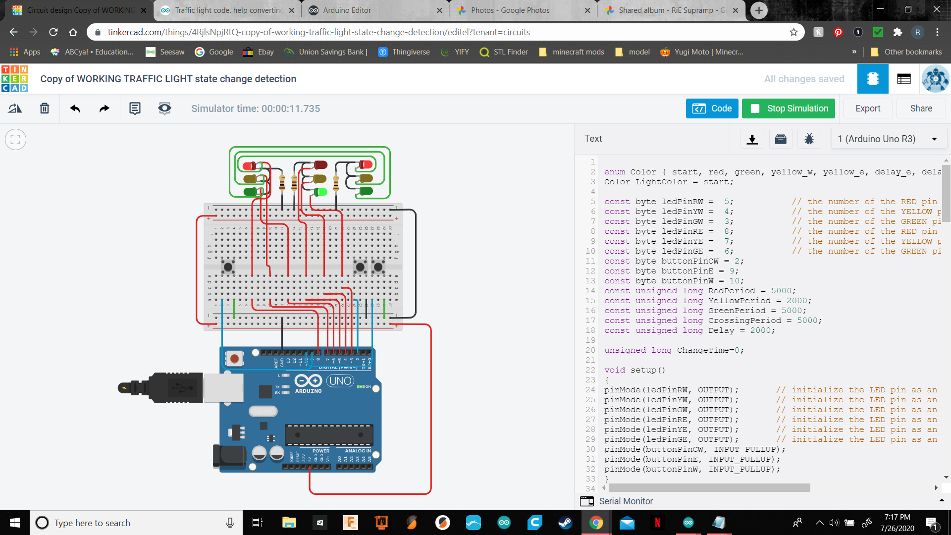
Hey WB, would you mind looking over this. It seems to work fine virtually. Ill have to build it tomorrow to actual tell. Does it look ok to you? Anything to clean it up or make it more efficient?
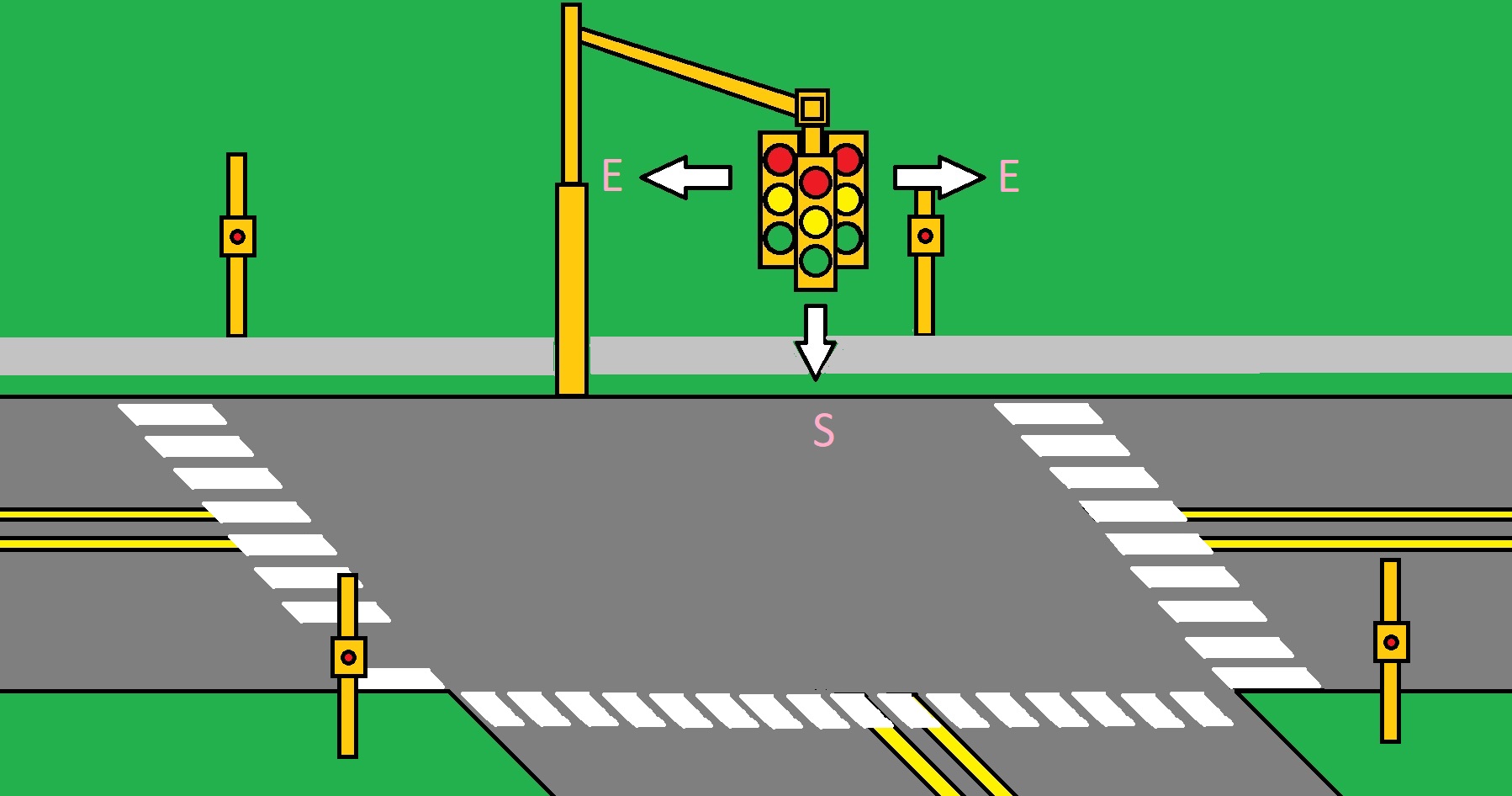
I have safety delays built in so the west lane wont switch from ed to green until 2 seconds after the east lane turns red, and vice versa. I also modified the idea behind crossing, so that the lights wont just change immediately. milli duration will be modified later. Thanks in advance

enum Color { start, red, green, yellow_w, yellow_e, delay_e, delay_w, crossing, crossing_w, crossing_e};
Color LightColor = start;

const byte ledPinRW =  5;           // the number of the RED pin
const byte ledPinYW =  4;           // the number of the YELLOW pin
const byte ledPinGW =  3;           // the number of the GREEN pin
const byte ledPinRE =  8;           // the number of the RED pin
const byte ledPinYE =  7;           // the number of the YELLOW pin
const byte ledPinGE =  6;           // the number of the GREEN pin
const byte buttonPinCW = 2;
const byte buttonPinE = 9;
const byte buttonPinW = 10;
const unsigned long RedPeriod = 5000;
const unsigned long YellowPeriod = 2000;
const unsigned long GreenPeriod = 5000;
const unsigned long CrossingPeriod = 5000;
const unsigned long Delay = 2000;

unsigned long ChangeTime=0;

void setup()
{
pinMode(ledPinRW, OUTPUT);       // initialize the LED pin as an output
pinMode(ledPinYW, OUTPUT);       // initialize the LED pin as an output
pinMode(ledPinGW, OUTPUT);       // initialize the LED pin as an output
pinMode(ledPinRE, OUTPUT);       // initialize the LED pin as an output
pinMode(ledPinYE, OUTPUT);       // initialize the LED pin as an output
pinMode(ledPinGE, OUTPUT);       // initialize the LED pin as an output
pinMode(buttonPinCW, INPUT_PULLUP);
pinMode(buttonPinE, INPUT_PULLUP);
pinMode(buttonPinW, INPUT_PULLUP); 
}

void loop()
{
if(digitalRead(ledPinGW) == HIGH &&digitalRead(buttonPinCW)==LOW)
  {
  delay(2000);
  LightColor=crossing_w; 
  digitalWrite(ledPinRW,LOW);
  digitalWrite(ledPinGW,LOW);
  digitalWrite(ledPinYW,HIGH);
  digitalWrite(ledPinRE,HIGH);
  digitalWrite(ledPinGE,LOW);
  digitalWrite(ledPinYE,LOW);
  digitalWrite(buttonPinCW,HIGH);
  ChangeTime=millis();
  }
  else if(digitalRead(ledPinGE) == HIGH && digitalRead(buttonPinCW)==LOW)
    {
    delay(2000);
  LightColor=crossing_e; 
  digitalWrite(ledPinRW,HIGH);
  digitalWrite(ledPinGW,LOW);
  digitalWrite(ledPinYW,LOW);
  digitalWrite(ledPinRE,LOW);
  digitalWrite(ledPinGE,LOW);
  digitalWrite(ledPinYE,HIGH);
  digitalWrite(buttonPinCW,HIGH);
  ChangeTime=millis();
  }
 
switch(LightColor )
  {
  case start:
        //WEST
    digitalWrite(ledPinRW,HIGH);
        //EAST
    digitalWrite(ledPinRE,LOW);
    digitalWrite(ledPinGE,HIGH);
    LightColor=red;
    ChangeTime=millis();
    break;

  case red:
    if(millis()-ChangeTime > RedPeriod && digitalRead(buttonPinW)==LOW)
      {
        //EAST
      digitalWrite(ledPinRE,LOW);
      digitalWrite(ledPinYE,HIGH);
      digitalWrite(ledPinGE,LOW);
        //WEST  
      digitalWrite(ledPinGW,LOW);
      digitalWrite(ledPinRW,HIGH);
      LightColor=yellow_e;
      ChangeTime=millis();     
      }
    break;
      
  case green:
    if(millis()-ChangeTime > GreenPeriod && digitalRead(buttonPinE)==LOW)
      {
        //WEST
      digitalWrite(ledPinGW,LOW);
      digitalWrite(ledPinYW,HIGH);
        //EAST
      digitalWrite(ledPinRE,HIGH);
      LightColor=yellow_w;
      ChangeTime=millis();     
      }
    break;
 
  case yellow_w :
    if(millis()-ChangeTime > YellowPeriod)
      {
        //WEST
      digitalWrite(ledPinYW,LOW);
      digitalWrite(ledPinRW,HIGH);
      LightColor=delay_e;
      ChangeTime=millis();     
      }
    break;

  case yellow_e :
    if(millis()-ChangeTime > YellowPeriod)
      {
        //EAST
      digitalWrite(ledPinYE,LOW);
      digitalWrite(ledPinRE,HIGH);
      LightColor=delay_w;
      ChangeTime=millis();     
      }
    break;
  
  case delay_e:
  if(millis()-ChangeTime > Delay)
      {
		//EAST
      digitalWrite(ledPinRE,LOW);
      digitalWrite(ledPinGE,HIGH);
      LightColor=red;
      ChangeTime=millis(); 
      }
    break;
  
  case delay_w:
  if(millis()-ChangeTime > Delay)
     {
		//WEST
      digitalWrite(ledPinRW,LOW);
      digitalWrite(ledPinGW,HIGH);
      LightColor=green;
      ChangeTime=millis(); 
     }
    break;
   
  case crossing:
    if(millis()-ChangeTime > CrossingPeriod)
      {
      LightColor=start;
      ChangeTime=millis();           
      }
    break; 
    
  case crossing_w:
  if(millis()-ChangeTime > Delay)
      {
		      //WEST
      digitalWrite(ledPinYW,LOW);
      digitalWrite(ledPinRW,HIGH);
      LightColor=crossing;
      ChangeTime=millis(); 
      }
    break; 
    
      case crossing_e:
  if(millis()-ChangeTime > Delay)
      {
		      //EAST
      digitalWrite(ledPinYE,LOW);
      digitalWrite(ledPinRE,HIGH);
      LightColor=crossing;
      ChangeTime=millis(); 
      }
    break; 
  
  }
}

Generally, using delay in a state machine will cause trouble, or at least make it unresponsive. You might get away with it here because you don't have to respond rapidly to any inputs yet.

The usual solution is to add a state to manage each delay using millis.

I'm not clear now what the traffic light arrangement is you're modeling. It looks like you have an eastbound light and another westbound. It might be clearer if you can post an image of the intersection you envisage it controlling and what the light pattern should be.

With multiple light installations, I'm not sure my state names make sense any longer. Red by itself doesn't tell you much - red where?

But as always with Arduino stuff, easy enough to test. Let us know how it functions.

First off, dont make fun of my MS Paint skill, lol. I just threw this together. While drawing it I realized that the logistics are a bit off, but as long as the sketch is doing what I want to do, and I understand how I made it do that, changing it will be much easier. My eyes were going crossed when I was trying to visualize the sequences earlier today, lol.
I guess in this image I would have the W labeled functions be south, and E would be east to west. Of course I would have to modify a few things to make the sketch reflect how the image should work. baby steps.

Heres a screen shot of the setup

[

](Traffic light code. help converting from interrupt with delays to flags - Project Guidance - Arduino Forum)arduino traffic light SC.png

how did you post the images like that?

You attached the image files to your two posts. Once they are attached, you have a URL for them that is accessible on the Internet and that URL can be used to embed them as an image (the little "screen" icon atop the "reply" box) in your post.

But you have to attach them first, and you have to (after copying the URL) then modify the same post if you wish to embed them in that. :grinning: