I am trying to code my own circuit board but i just get the "fault" code
         Using Port                    : COM1
         Using Programmer              : wiring
         Overriding Baud Rate          : 115200
avrdude: stk500v2_ReceiveMessage(): timeout
avrdude: stk500v2_ReceiveMessage(): timeout
avrdude: stk500v2_ReceiveMessage(): timeout
avrdude: stk500v2_ReceiveMessage(): timeout
avrdude: stk500v2_ReceiveMessage(): timeout
avrdude: stk500v2_ReceiveMessage(): timeout
avrdude: stk500v2_getsync(): timeout communicating with programmer

avrdude done.  Thank you.

Failed uploading: uploading error: exit status 1
im using an arduino uno to program my own circuit board which have a atmega2560 on it. The strange thing is that i following a guide i found on internet https://www.instructables.com/ATMEGA2560-Standalone-Using-Arduino-UNO/ and i had no problems burning the bootloader but now when i'm just trying to code my atmega2560 i just get the "fault" code above. any suggestions?
That is the right one. Please post the output you get when you attempt to make the upload with that port selected. There might be some subtle differences that are important for troubleshooting the upload failure.
After burning the bootloader, did you upload any sketch using the ISP programmer? If so, that will have erased the bootloader.
Just to verify, you are now trying to upload through Serial instead of the ISP programmer.
Check to make sure the crystal is connected properly, if that is not working then you will not be able to program the atmega2560 by either serial or ISP.
Is anything else connected to the atmega2560 serial port that you are using for the upload?
Can you post a schematic? If you do not have the RESET wired properly then the atmega2560 will not reset, which is required to enter the bootloader code.
avrdude: Version 6.3-20190619
         Copyright (c) 2000-2005 Brian Dean, http://www.bdmicro.com/
         Copyright (c) 2007-2014 Joerg Wunsch

         System wide configuration file is "C:\Users\hanne\AppData\Local\Arduino15\packages\arduino\tools\avrdude\6.3.0-arduino17/etc/avrdude.conf"

         Using Port                    : COM5
         Using Programmer              : wiring
         Overriding Baud Rate          : 115200
avrdude: stk500v2_ReceiveMessage(): timeout
avrdude: stk500v2_ReceiveMessage(): timeout
avrdude: stk500v2_ReceiveMessage(): timeout
avrdude: stk500v2_ReceiveMessage(): timeout
avrdude: stk500v2_ReceiveMessage(): timeout
avrdude: stk500v2_ReceiveMessage(): timeout
avrdude: stk500v2_getsync(): timeout communicating with programmer

avrdude done.  Thank you.

Failed uploading: uploading error: exit status 1
i have not change "mega.menu.cpu.atmega2560.bootloader.high_fuses=0xD8" to 0xD9 as it said on the guide i followed on this computer because this has windows 10 and much newer version of arduino. But when i tried on my other computer which has windows 7 so i had to download a older version of arduino i tried to change it to 0xD9 in boards.txt and no diffrent so im guessing that is not the issue at all
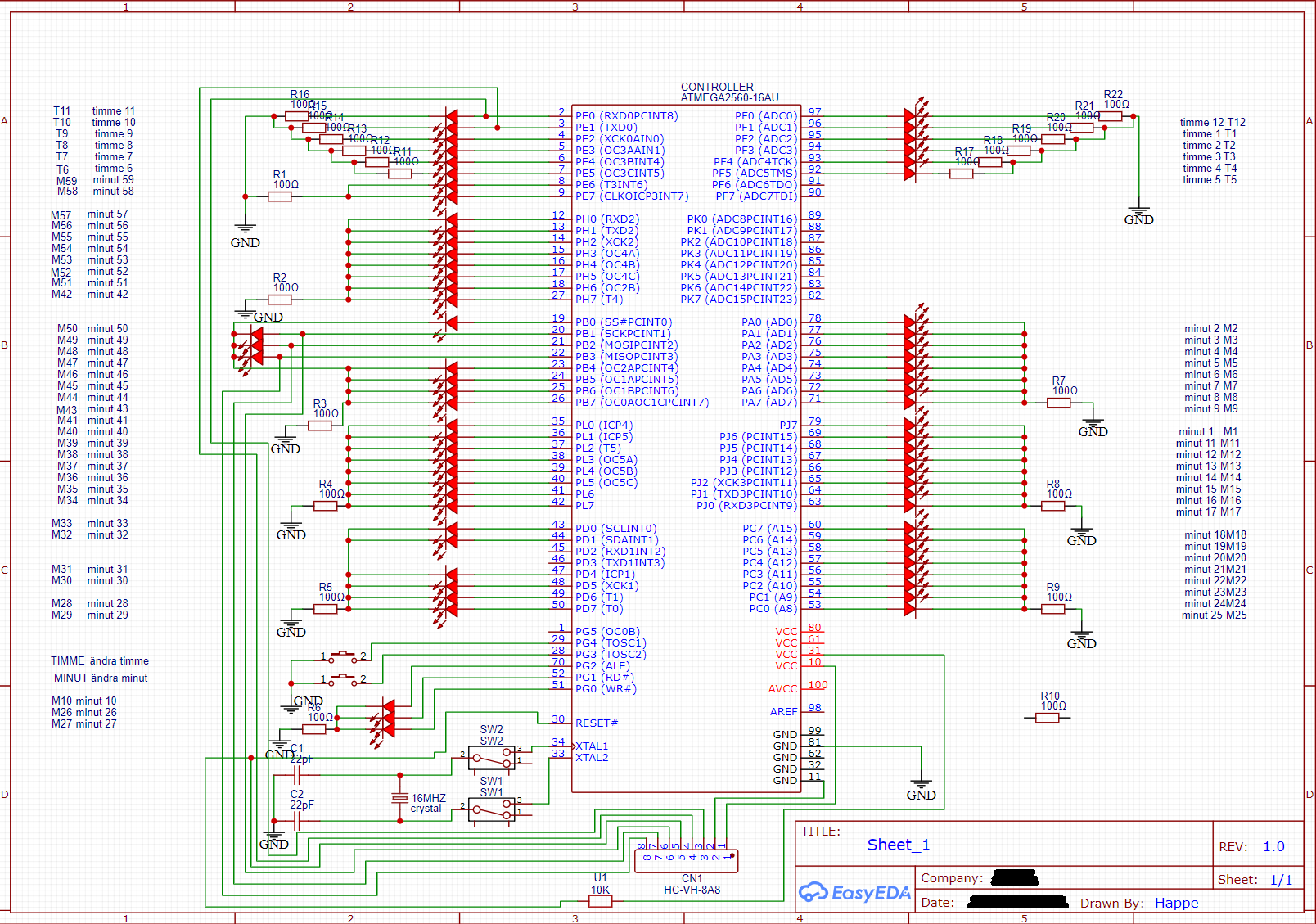
there is my schematic. im learning so i probably have done som questionable connections and all that so don't judge xD. and i connect wires from my arduino uno to my own circuit board. and for more information the led connected to pin 2 and 3 on my own circuit board is always on when i plug it in and pin 26 is flashing.
Nice to see a clear schematic! I see potential problems with switches in the crystal connections. Also you do not have any bypass capacitors. You might want to check your current, the ATmega2560 has an absolute limit of 40mA on each pin, and 200mA in total for all pins. Exceeding this even momentarily could destroy it.
I don't understand why that would need to be changed. The difference between 0xD8 and 0xD9 is the BOOTRST bit, which caused the processor to execute the bootloader after a reset. There would not be any reason to change this because you want the bootloader to execute.
The LED and 100 ohm series resistor on the Rx pin is definitely going to cause problems. The Tx line from the atmega16u2 on the UNO has an in-line 1K ohm resistor. There will never be enough voltage on the Rx pin of the atmega2560 for a HIGH.
Also be careful of the current rating of the LEDs. At 5V, with approximately 1.7V drop across the LED, the 100 ohm resistor will limit the current to 33mA.
I'm a bit surprised the ISP programming worked with the LEDs on the SPI pins.
haha yeah should had researched a bit more before i order my circuit board. but it's all really intresting nonetheless and you learn by your mistakes. but i guess i need to do some changes on my schemetics if i want it to work but i could try to bypass the resistor and led on the RTX line to see if i can atleast code it. but yeah i guess i would never get it working as i want it to. if you guys haven't figured it out yet it is suppose to be a "watch". i have named some things in swedish but minute is obviously minute, timme is hour and ändra is change. so i would had the minutes on the outer circle and hours on the inner circle but i would draw to much power as you said so yeah :(. i can post a picture on how the circuit board looks :).
Could it be this simple that you try to Upload (Ctrl+U) instead of Upload With Programmer (Ctrl+Shift+U)? Cause you still have the Arduino as ISP, right?
Lets see, 60 LEDs for the minutes, 12 for the hour, that is a total of 72.
A grid of 8 x 9 will drive the entire thing with 17 I/O pins using multiplexing (even less with charlieplexing), but with only a single minute and a single hour LED being lit at any given time, you can bypass the normal multiplexing operation and just drive the two desired LEDs 50% of the time each. No real need for the relatively huge atmega2560.
now we talking some advanced stuffs xD i am a very beginner at this stuffs but i understand your post i think. But i have no idea how to set it up and how do the controller know what LED to light up if they are all connected is beyond me xD i thought everything had to had a pin for themselves. i think i will put my projekt on ice for a time because it's i have to redesign everything more or less and it's not free to order some new circuit boards.
I'm going to ask you to post the full verbose output from an upload attempt.
This procedure is not intended to solve the problem. The purpose is to gather more information.
Please do this:
Select File > Preferences... from the Arduino IDE menus.
The "Preferences" dialog will open.
Uncheck the box next to Show verbose output during: ☑ compilation in the "Preferences" dialog.
Check the box next to Show verbose output during: ☐ upload.
Click the "OK" button.
Attempt an upload, as you did before.
Wait for the upload to fail.
You will see a "Upload error: ..." notification at the bottom right corner of the Arduino IDE window. Click the "COPY ERROR MESSAGES" button on that notification.
Open a forum reply here by clicking the "Reply" button.
Click the <CODE/> icon on the post composer toolbar.
This will add the forum's code block markup (```) to your reply to make sure the error messages are correctly formatted.
Press Ctrl+V.
This will paste the error output from the upload into the code block.
Move the cursor outside of the code tags before you add any additional text to your reply.
Click the "Reply" button to post the output.
Since you mentioned "much newer version of arduino", the instructions above assume you are using Arduino IDE 2.x. If you are instead using Arduino IDE 1.x, the procedure is slightly different.