TL;DR: I am trying to use a handset from an old rotary phone as audio input / output from a SIM shield, but the microphone is way too noisy and I get a return on the speaker. Any help welcome
Hi!
I am refining a project I worked on a couple of years ago to re-vamp an old rotary phone with an Arduino and a SIM card shield. The major problem I am having is using the old headset.
The speaker, on its own, works fairly OK. However, whenever I couple also the microphone, I get a lot of background noise, and I also get a return on the speaker. I have decoupled the headset completely from the rest of the phone's hardware and it still does not work properly.
I am using an Ericsson DBH 1001 phone (this beauty): here the microphone should be a carbon granule transmitter capsule and the speaker should be a moving-iron receiver capsule.
It tells you things like how to post code and how to ask a question.
In particular we, on this forum, need to see a schematic of how things are wired up in order to understand what is going on before we can offer any valid help.
That is the bit where a schematic would be invaluable because I, for one, have no idea what you mean by this.
Carbon granules microphones are noisy, especially old ones. Telephone audio bandwidth is 300 to 3k4Hz, filtering anything above 3k4Hz will probably get rid of some noise. Impedance matching is also important, what are you doing to match the output impedance of the microphone?
You have discovered one of the reasons we don't use that kind of phone anymore. If you want an oldie look-alike, replace the microphone and earphones with modern versions that will not have that problem. It will still look like an oldie, but the parts inside will work much better.
You are absolutely right @Grumpy_Mike.
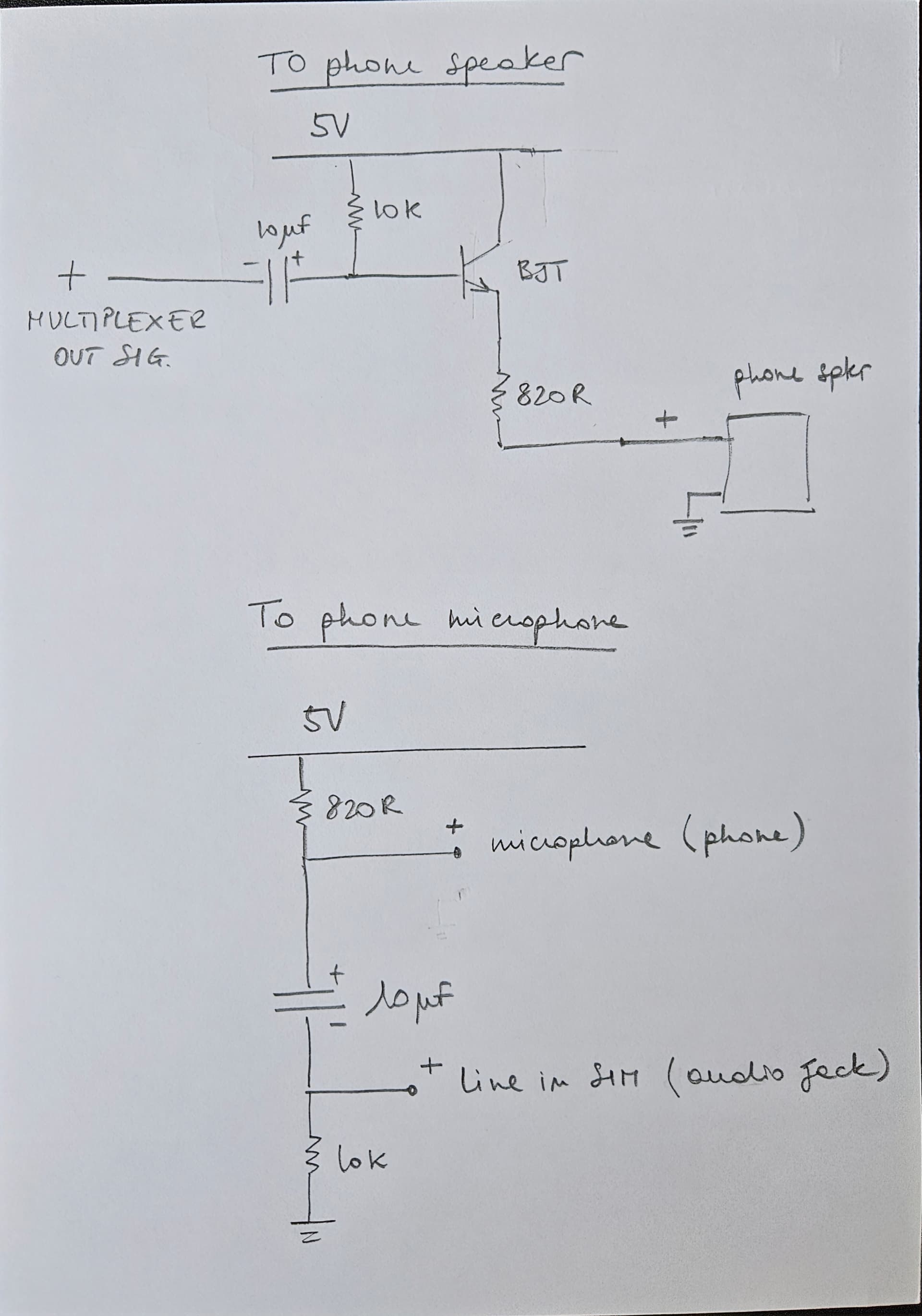
I attach a simple schema for the two circuit snippets I am using to connect the handset with the multiplexer output (sound to speaker) and to the jack input (for the microphone to my system).
The schematics are pen&paper because I am still experimenting. I can provide more details if you want.
I also attach the piece of the original phone schematics (which was INSIDE the phone ). In the small red box is the part that I am trying to connect (the handset).
The wire labeled "Gul" - Swedish for yellow - is the + of "phone speaker" in my schematics. "Röd" is the + of the microphone in my schema. "Svart" is ground.
Thank you @PerryBebbington ! I have attached the schematics and a little more information. I must say that hardware is not my strong suit, so if you can point me in the right direction, it would be incredibly appreciated.
A carbon microphone is a VARIABLE RESISTOR! It needs current through it in order to work. In use the variable current will produce a variable voltage across the resistor. That is the voltage you can use to amplify and give you the audio you want.
You show 1 wire going to the microphone, where does the other side of the microphone go?
You should not pass DC through the receiver (speaker) like you are doing. The phone circuit removed DC from the receiver, but it's a long time since I studied that circuit and I'm struggling to work it out well enough to tell you.
Do you mean that the sound from the microphone comes out of the speaker? That's called sidetone and without it a phone sounds dead and isn't nice to use. As I don't know anything about the SIM card shield you are using I can't tell you much but does it have a setting for side tone? If so play around with that. I'd also play around with reducing the 10k resistor, maybe 1k or 820R to match the 820R current feed to the microphone. Even better would be a constant current source, not a resistor.
I can't give you an exact answer but I hope experimenting with the above helps.
Nothing in your circuit limits the bandwidth of the audio from the microphone, although maybe the SIM card shield does, but I don't know. You said it's noisy but not where you are hearing the noise from. Where are you hearing it?
The other wire from the mic goes to ground.
I did not realise that the original circuit removed DC from the speaker! I must say that the speaker works well enough at the moment, but I could add a cap (say 22–47 µF) before the speaker + to filter out DC.
About the noise: it is very strong on the the speaker of the person I am talking to, and I can hear it also in my own speaker. I guess that this is because of the sidetone you mention. I do not think that my SIM shield (this one) can handle that: I did not see any info on the manual. Also, I am simply using the audio jack on the card.
One thing that I have been thinking is to play a little with frequency filters (resistor + capacitor). I am very rusty in electronics, but I will take a look and see if that helps. I have sketched a small adjustment that (if I got it right with some.... help) could do the trick:
These phones or the GPO equivalent, were thrown out in their thousands as newer technologies were introduced. My own old company had skips full of the phones and goodies like like IBM Golfball typewriters. Criminal.
Employees weren't allowed to take them, but some were liberated.
I have one of the GPO types and hope to convert it to a door bell, time allowing. For now, just pinging the bells will have to do. Lovely sound.
I thought it probably would, but please in future show complete schematics.
I can't really tell you if your new proposed circuit will help but I do think you need to increase the 0μ1F capacitor a lot, maybe 10μF, and increase the 10nF capacitor, it's too low to do anything. I can't do the maths to suggest a suitable value, maybe someone else can. I'd be aiming for filtering anything above 3k4Hz or so. I no one can do the maths then it's trial and error.
They were not old when I played with them! I worked in telecoms my whole life, starting aged about, I don't know, maybe 8 when my dad brought me 2 old handsets home to play with. That circuit pre-dates the circuit used in the phones I used to work with, but phones with that or a similar circuit were in use in the 1960s and 1970s as far as I can remember.
There are several possible sources of sidetone, although only one is really sidetone.
Actual sidetone is produced deliberately in the phone, without it the phone sounds dead. In that circuit it is the transformer that does it.
Issues on the network can produce echo, if the delay is really short then it will show up as sidetone. If the delay is more than (I think) 20ms then it starts to be obvious as an echo.
The remote phone can also send the signal back, which will show up as an echo. This can happen either as a result of problems with the circuitry of the remote phone or by acoustic coupling between the receiver and microphone of the remote phone.
I'm sorry but beyond the general advice I've given I can't be more specific.
As usual, thank you everyone for pitching in! I am dead set to have this phone up and working in our home
@Paul_KD7HB no, I am not sure. What I know is that the disturb is at its highest on the receiving phone, and there is an echo also in my own receiver.
I have implemented the circuit I sketched above, with a passive band filter, but that has not helped much. @PerryBebbington the values I have put in are calculated by the cut-off frequency points for a band pass filter: f_c = 1 / (2πRC), for 300Hz and 3k4Hz (circa). I double checked and for 4.7KOhm resistors, the caps should be correct.
I could increase their size, but then I should reduce the resistors. I can try, but mathematically it would make no difference...
I am having another doubt at the moment that I need to explore: my connection to the SIM shield is through a normal jack audio. I need to make sure that I am not misusing that interface and causing problems on the shield.
The number of pulses sent for each digit is defined by the type of dial system in use. The encoding has traditionally varied by country, or by the manufacturer of the telephone system. For example, Sweden used one pulse to signal the number zero, and ten pulses to signal the number nine. In Finland, where many telephones were of Swedish manufacture, one pulse signaled digit 1 , and ten pulses 0 . New Zealand used ten pulses minus the number desired; so dialing the digit 7 produces three pulses. In Norway, the North American system with the digit 1 corresponding to one pulse was used, except for the capital city, Oslo, which used the same "inverse" system as in New Zealand. The sequencing of the digits on the dial varies accordingly.
 ). In the small red box is the part that I am trying to connect (the handset).


