I've had a chance to look over your photos now Ruth.
Overall, the wiring looks good, and is all correct. A couple of points concern me though:-
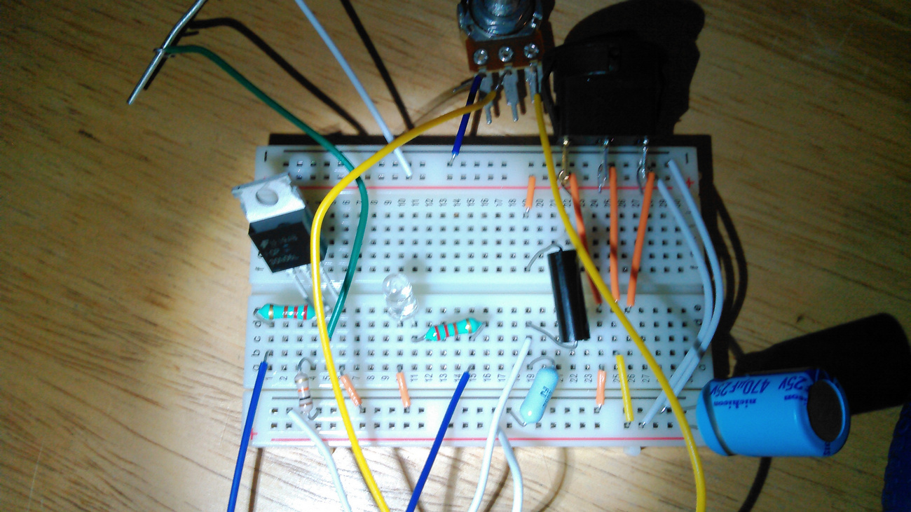
In this shot, it looks like there's a chance that the right-hand-side switch terminal could short with the wire leading to the positive rail on the breadboard. (Circled.) I'd personally use longer wires to the switch, so it's clear of the breadboard.

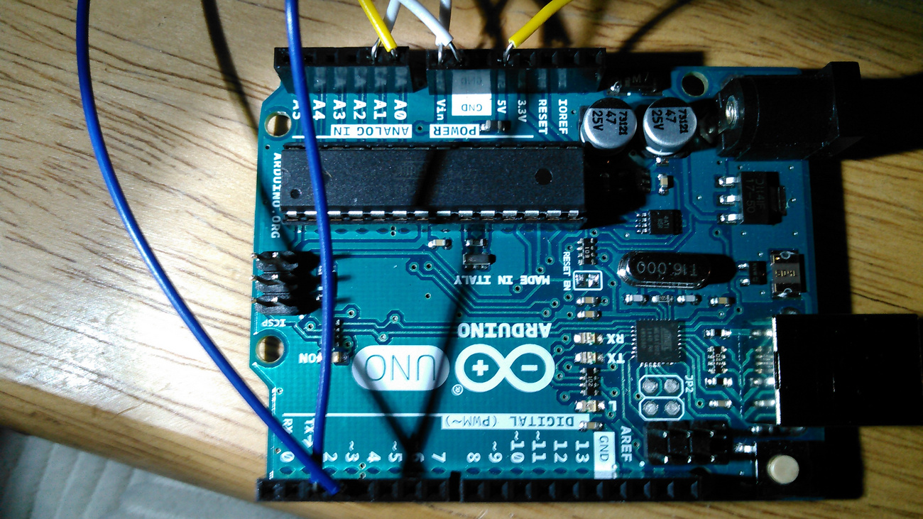
And similarly in this shot, it looks like the two wires in the circle could potentially short together, and possibly also the yellow and white wires just to the left.
Maybe trimming off the ends of some wires would be a good idea, so there's no bare wire extending out of the UNO and breadboard socket holes.

Something else that concerns me is the fact that the wires are only bent around the terminals on the switch, pot and diode. I assume that's temporary, but they will need to be soldered before power can be applied to the circuit. Solder them in such a way that they can be unsoldered when it comes to building the final version on veroboard, after testing on the breadboard. (When you solder the temporary connections, avoid looping the wire around things, or it'll be hard to unsolder. Just tin both and solder the connections flat, if you get what I mean.)
Also, it's fairly important that you connect the fuse up when you do connect the battery, and be very careful that the battery is connected in the correct polarity, or a couple of parts will go pop and let their magic smoke out. (Not a good thing.  )
)
Don't power up just yet though, until the code is written and I've had a peek at it.
Now to that code. The parts relating to the buttonPin aren't needed now of course. Also, in 'setup()', there's no need to initialise the 'motorPin' as 'OUTPUT' - that's done automatically when you call 'analogWrite()'.
The same goes for 'batteryPin' and 'potPin'. They're automatically set up when you call 'analogRead()'.
So the only pin that needs to be set up in 'setup()' is 'ledPin'.
Removing those parts from the code you posted, it would look like this:-
(Oh, I made all the pin allocations 'byte' too.)
const byte batteryPin = A1;      // battery
const byte motorPin = 3;         // motor
const byte ledPin = 2;           // status led for battery
const byte potPin = A0;          // throttle pot

int potVal;

void setup()
{
    pinMode(ledPin, OUTPUT);
}
I know you want to write your own code, so I won't show it to you, but I've already written (my version of) the program and am currently putting together a test circuit so that I can test your program when you get it written.
Most of the program is fairly straightforward, but when you write the part that reads the battery voltage, it needs to set the LED "HIGH" if the analogue value is below 868, or set it "LOW" if the analogue value is above 872. That equates to 11.9V +/- 28mV, for a total of 56mV hysteresis. (Those values might need to be fine-tuned later, but they're good starting points.)
And when you write the pot/motor code, don't forget that after reading the pot, you need to divide the result by 4 before using 'analogWrite()' to generate the PWM for the motor. This converts the analogue 0-1023 value to 0-255 for the 8-bit PWM.
I think I've covered everything important.
Edit: Nope, I forgot to say - don't forget to test the switch and check on which terminal is which.