There it is:
You have to connect GND of the ESP8266 with GND of the DRV8833-Module
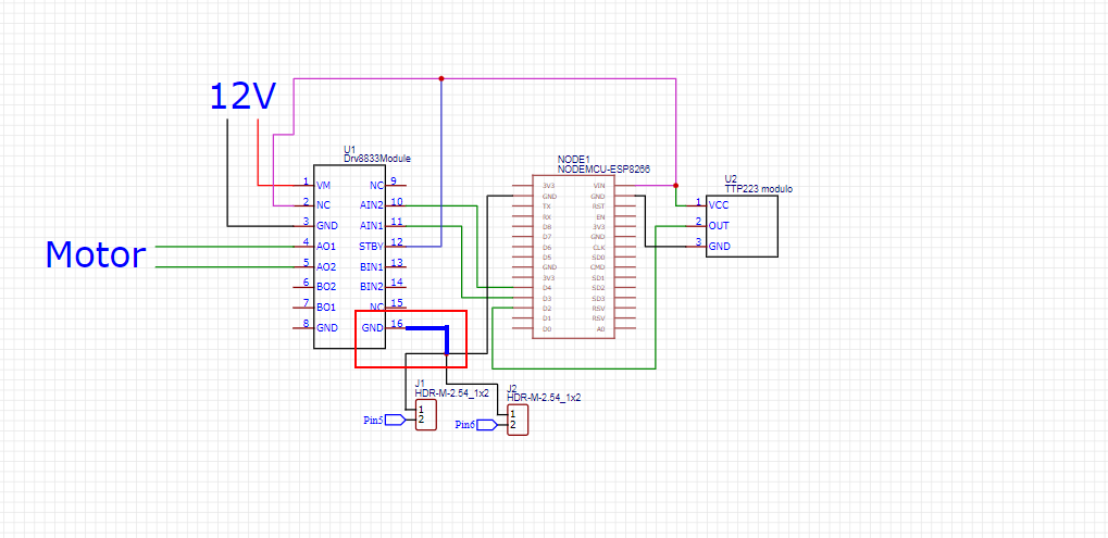
Connecting Vcc of the TTP223 with the NC-pin of the DRV8833-module is useless.
The meaning of "NC" is not connected
There it is:
You have to connect GND of the ESP8266 with GND of the DRV8833-Module
Connecting Vcc of the TTP223 with the NC-pin of the DRV8833-module is useless.
The meaning of "NC" is not connected
Connected GND did not help
With what code? Please try to say more than less, we not mind readers over here.
a7
Did you try using D5 instead of D4?
Do you have a digital multimeter?
You should measure what voltages arrive at the AIN2 pin.
As a very simple test disconnect the ESP8266 and connect the AIN1 / AIN2 pins of the DRV8833-module directly to GND / 3.3V
Connected GND to the driver, changed the driver pin D4 to D7.
Received this response from Serial:
"01" touchSwitch changed from 0 to 1
BARRIER GOING UP
lastbarrierState changed from DOWN to GOING_UP
"01" touchSwitch changed from 1 to 0
Code:
// MACRO-START * MACRO-START * MACRO-START * MACRO-START * MACRO-START * MACRO-START *
// a detailed explanation how these macros work is given in this tutorial
// https://forum.arduino.cc/t/comfortable-serial-debug-output-short-to-write-fixed-text-name-and-content-of-any-variable-code-example/888298

#define dbg(myFixedText, variableName) \
  Serial.print( F(#myFixedText " "  #variableName"=") ); \
  Serial.println(variableName);

#define dbgi(myFixedText, variableName,timeInterval) \
  { \
    static unsigned long intervalStartTime; \
    if ( millis() - intervalStartTime >= timeInterval ){ \
      intervalStartTime = millis(); \
      Serial.print( F(#myFixedText " "  #variableName"=") ); \
      Serial.println(variableName); \
    } \
  }

#define dbgc(myFixedText, variableName) \
  { \
    static long lastState; \
    if ( lastState != variableName ){ \
      Serial.print( F(#myFixedText " "  #variableName" changed from ") ); \
      Serial.print(lastState); \
      Serial.print( F(" to ") ); \
      Serial.println(variableName); \
      lastState = variableName; \
    } \
  }

#define dbgcf(myFixedText, variableName) \
  { \
    static float lastState; \
    if ( lastState != variableName ){ \
      Serial.print( F(#myFixedText " "  #variableName" changed from ") ); \
      Serial.print(lastState); \
      Serial.print( F(" to ") ); \
      Serial.println(variableName); \
      lastState = variableName; \
    } \
  }
// MACRO-END * MACRO-END * MACRO-END * MACRO-END * MACRO-END * MACRO-END * MACRO-END *


enum barrierStates {
  UNKNOWN,
  DOWN,
  GOING_UP,
  UP,
  GOING_DOWN
};

char myStateNames[][16] = {
  "UNKNOWN",
  "DOWN",
  "GOING_UP",
  "UP",
  "GOING_DOWN"
};

enum barrierStates barrierState;

const uint8_t upLimitSwitchPin = D5;    // UNO pin 4
const uint8_t downLimitSwitchPin = D6;  // UNO pin 5
const uint8_t touchSwitchPin = D2;      // UNO Pin 6

uint8_t upLimitSwitch;
uint8_t downLimitSwitch;
uint8_t touchSwitch;
uint8_t prevTouchSwitch;

#define AIN1 D3
#define AIN2 D7

void setup() {
  Serial.begin(9600);
  Serial.println("Setup-Start");

  pinMode( upLimitSwitchPin, INPUT_PULLUP );
  pinMode( downLimitSwitchPin, INPUT_PULLUP );
  pinMode( touchSwitchPin, INPUT_PULLUP );

  pinMode(AIN1, OUTPUT);
  pinMode(AIN2, OUTPUT);

  delay(100);
  touchSwitch = digitalRead( touchSwitchPin );
  prevTouchSwitch = touchSwitch;

  // a HIGH here means the limit switch is open
  upLimitSwitch = digitalRead( upLimitSwitchPin );
  downLimitSwitch = digitalRead( downLimitSwitchPin );

  // determine the initial barrier position
  if ( upLimitSwitch == LOW && downLimitSwitch == LOW ) {
    Serial.println(F("ERROR - both limit switches activated"));
    while (1);
  }
  else if ( upLimitSwitch == HIGH && downLimitSwitch == HIGH ) {
    barrierState = UNKNOWN;
    Serial.println(F("BARRIER POSITION UNKNOWN"));
  }
  else if ( upLimitSwitch == LOW ) {
    Serial.println(F("BARRIER UP"));
    barrierState = UP;
  }
  else {
    Serial.println(F("BARRIER DOWN"));
    barrierState = DOWN;
  }
}

void loop() {
  printStateIfChanged();

  // assume HIGH = switch touched
  touchSwitch = digitalRead( touchSwitchPin );
  // only in case variable "touchSwitch" has CHANGED its value
  dbgc("01",touchSwitch); // print value only once

  upLimitSwitch = digitalRead( upLimitSwitchPin );
  dbgc("02",upLimitSwitch);
  downLimitSwitch = digitalRead( downLimitSwitchPin );
  dbgc("03",downLimitSwitch);

  switch ( barrierState ) {
    case UNKNOWN:
      digitalWrite(AIN2,HIGH);
      upLimitSwitch = digitalRead( upLimitSwitchPin );
      if ( upLimitSwitch == LOW ) {
        digitalWrite(AIN2,LOW);
        Serial.println(F("BARRIER UP"));
        barrierState = UP;
      }
      break;

    case DOWN:
      if (( touchSwitch != prevTouchSwitch ) && ( touchSwitch == HIGH ) ) {
        digitalWrite(AIN2,HIGH);
        Serial.println(F("BARRIER GOING UP"));
        barrierState = GOING_UP;
      }
      break;

    case GOING_UP:
      upLimitSwitch = digitalRead( upLimitSwitchPin );
      if ( upLimitSwitch == LOW ) {
        digitalWrite(AIN2,LOW);
        Serial.println(F("BARRIER UP"));
        barrierState = UP;
      }
      break;

    case UP:
      if (( touchSwitch != prevTouchSwitch ) && ( touchSwitch == HIGH ) ) {
        digitalWrite(AIN1,HIGH);
        Serial.println(F("BARRIER GOING DOWN"));
        barrierState = GOING_DOWN;
      }
      break;

    case GOING_DOWN:
      downLimitSwitch = digitalRead( downLimitSwitchPin );
      if ( downLimitSwitch == LOW ) {
        digitalWrite(AIN1,LOW);
        Serial.println(F("BARRIER DOWN"));
        barrierState = DOWN;
      }
      break;
  }
  prevTouchSwitch = touchSwitch;
}


void printStateIfChanged() {
  static byte lastbarrierState;

  if (lastbarrierState != barrierState) {
    Serial.print("lastbarrierState changed from ");
    Serial.print(myStateNames[lastbarrierState]);
    Serial.print(" to ");
    Serial.println(myStateNames[barrierState]);
    lastbarrierState = barrierState;    // update lastbarrierState with value of **barrier**State
  }
}
Hi @muhammedjan,
@alto777 is correct, your sketch works correctly.
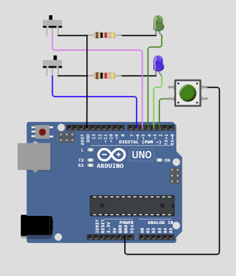
See here on Wokwi ( I only changed some pin names/assignments so that they work with an UNO):
https://wokwi.com/projects/373403879525605377

Upper sliding switch = UpLimit
Lower sliding switch = DownLimit
Green Led = Barrier goes up
Blue Led = Barrier goes down
Button = Touch Button
If both sliding switches are at the left side (open) you start with UNKNOWN.
You may click on the upper one so it moves to the right and Serial prints "BARRIER UP" etc.
This way you can check the behaviour of the sketch.
(Just a remark; For proper action you must open the sliding switch first where the Led is OFF - that simulates the release of the respective limit switch - then close the one where the Led is ON - this simulates the arrival at the limit switch.)
Yes, I connected D4 to D7.
(D5 connected one pin limit switch)
I have a digital multimeter. But I bought it recently. Can you please explain in more detail how this is done?
Thanks! If the code works fine, then what could be the problem?
What is the difference between the two test setups?
That's what our fellow members remotely try to find out ... and requires your assistance.
Something electrical
Post a picture of your multimeter
Voltage-measuring adjust digital multimeter (in short DMM) to measuring voltages
range 20V
Connect black probe with ground
Connect red probe with AIN2
I think this is a typical XY problem overlaid by a copy/paste action.
And I'm off to feed the Piguine.
Did as you said. When I press the touch button, the multimeter shows 3.30 V
Thanks for the sanity check. I, too, ran it in the simulator after convincing myself that @PaulRB was correct.
I don't have time just now, but I thought this sketch might be amenable to having a simukated barrier running alongside the OP's code. A Neopixel strip to illustrate the position of the barrier, and outputs from the barrier simulation section that could be wired directly to the inputs of the OP's algorithm.
One small point for wokwi users: if you start a wire from an UNO GND pin, it will be black. Well designed parts will indicate pins that expect to be grounded. Same same for Vcc. Only… red.
If you select a wire that is not the color you like, a menu will pop up and let you pick a color, or type its numerical code.
I do a lotta select '0' to make wires at ground potential appear the way you know who intended. Black.
Had to squint a bit to see the way the switches and LEDs were wired.
Also, if you type 'g' whilst editing the schematic, you get stuff snapped to a grid, makes things tidier.
a7
Hi @alto777,
didn't want to make it difficult to read ![]()
I tidied up and it looks now like this
Hope that's better and thanks for your valuable hint regarding the 'g' feature!
Hooray! But ... correct about what?
If you look up the datasheet of the DRV8833
The two Inputs AIN1 / AIN2 have to be set oppositional
AIN1 HIGH AIN2 LOW
or
AIN1 LOW AIN2 HIGH
whenever you want to switch on the motor you should execute
dgitalWrite to both inputs
o check with the multimeter black probe always connected to ground what voltages do you measure on AIN1 result for AIN1?
and
measure on AIN2 result for AIN2?
.
.
Do NOT use the 12V for the next suggested test!!
Do you have an extra 5V or 3.3V voltage-supply?
If yes connect GND of this 3.3V voltage-supply with the GND of your 12V supply
ONLY GND!
As another test as previsiously written
dismount the barrier = make the motor free rotating
connect AIN1 to GND connect AIN2 directly to 3.3V
Does the motor rotate?
second test
connect AIN1 to 3.3V connect AIN2 to GND
Does the motor rotate?
best regards Stefan
There was no problem with the code.
a7
I have managed to create a simulated door from parts I found lying around.
 barrier up/down demo simulated simulation
Imma not going to post the code, it is... the OP's code with @alto777's old neopixel door emulkator stood up beside it.
The wonky white wires you will see when you take the link are only the OP's code telling the door simulator whether and which way to run the motor, and the door simulator's outputs which inform the OP's code as to the state of the limit switches.
All before she texted.
Excuse the lack of series current limiting resistors on the LEDs. I used magic can't be burned won't take but a few milliamps wokwi brand LEDs.
Fun!
a7
Great idea!
If you like have a look at this:
/*
  Forum: https://forum.arduino.cc/t/two-limit-switches-and-a-gear-motor/1159503/21
  Wokwi: https://wokwi.com/projects/373407825895140353

*/

// ********* Simulation Components Declarations        *********
#include <Adafruit_NeoPixel.h>
constexpr byte simUpLimitPin   = 8;
constexpr byte simDownLimitPin = 9;
constexpr byte simBarrierPin   = 7;
const uint16_t NUMPIXELS1 = 16;
Adafruit_NeoPixel strip1(NUMPIXELS1, simBarrierPin, NEO_GRB + NEO_KHZ800);
int simPosition = 0;
// ********* End of Simulation Components Declarations *********


enum barrierStates {
  UNKNOWN,
  DOWN,
  GOING_UP,
  UP,
  GOING_DOWN
};

enum barrierStates barrierState;

const uint8_t upLimitSwitchPin = 5;    // UNO pin 5
const uint8_t downLimitSwitchPin = 6;  // UNO pin 6
const uint8_t touchSwitchPin = 2;      // UNO Pin 2

uint8_t upLimitSwitch;
uint8_t downLimitSwitch;
uint8_t touchSwitch;
uint8_t prevTouchSwitch;

#define AIN1 3
#define AIN2 4

void setup() {

  // ******************Simulation Components Setup******************
  strip1.begin();
  strip1.clear();
  strip1.setBrightness(255);
  strip1.show();
  pinMode(simUpLimitPin, OUTPUT);
  pinMode(simDownLimitPin, OUTPUT);
  digitalWrite(simUpLimitPin, HIGH);
  digitalWrite(simDownLimitPin, HIGH);
  randomSeed(analogRead(A0));
  simPosition = random(0,16);
  // ***************End of Simulation Components Setup******************


  Serial.begin(9600);
  pinMode( upLimitSwitchPin, INPUT_PULLUP );
  pinMode( downLimitSwitchPin, INPUT_PULLUP );
  pinMode( touchSwitchPin, INPUT_PULLUP );

  pinMode(AIN1, OUTPUT);
  pinMode(AIN2, OUTPUT);

  delay(100);
  touchSwitch = digitalRead( touchSwitchPin );
  prevTouchSwitch = touchSwitch;

  // a HIGH here means the limit switch is open
  upLimitSwitch = digitalRead( upLimitSwitchPin );
  downLimitSwitch = digitalRead( downLimitSwitchPin );

  // determine the initial barrier position
  if ( upLimitSwitch == LOW && downLimitSwitch == LOW ) {
    Serial.println(F("ERROR - both limit switches activated"));
    while (1);
  }
  else if ( upLimitSwitch == HIGH && downLimitSwitch == HIGH ) {
    barrierState = UNKNOWN;
    Serial.println(F("BARRIER POSITION UNKNOWN"));
  }
  else if ( upLimitSwitch == LOW ) {
    Serial.println(F("BARRIER UP"));
    barrierState = UP;
  }
  else {
    Serial.println(F("BARRIER DOWN"));
    barrierState = DOWN;
  }
}

void loop() {
  // assume HIGH = switch touched
  touchSwitch = digitalRead( touchSwitchPin );

  // ******** Simulation of barrier by Neopixel Ring   *********
  barrierSimulation();
  // ******** End of Simulation of barrier by Neopixel Ring ****

  switch ( barrierState ) {
    case UNKNOWN:
      digitalWrite(AIN2, HIGH);
      upLimitSwitch = digitalRead( upLimitSwitchPin );
      if ( upLimitSwitch == LOW ) {
        digitalWrite(AIN2, LOW);
        Serial.println(F("BARRIER UP"));
        barrierState = UP;
      }
      break;

    case DOWN:
      if (( touchSwitch != prevTouchSwitch ) && ( touchSwitch == HIGH ) ) {
        digitalWrite(AIN2, HIGH);
        Serial.println(F("BARRIER GOING UP"));
        barrierState = GOING_UP;
      }
      break;

    case GOING_UP:
      upLimitSwitch = digitalRead( upLimitSwitchPin );
      if ( upLimitSwitch == LOW ) {
        digitalWrite(AIN2, LOW);
        Serial.println(F("BARRIER UP"));
        barrierState = UP;
      }
      break;

    case UP:
      if (( touchSwitch != prevTouchSwitch ) && ( touchSwitch == HIGH ) ) {
        digitalWrite(AIN1, HIGH);
        Serial.println(F("BARRIER GOING DOWN"));
        barrierState = GOING_DOWN;
      }
      break;

    case GOING_DOWN:
      downLimitSwitch = digitalRead( downLimitSwitchPin );
      if ( downLimitSwitch == LOW ) {
        digitalWrite(AIN1, LOW);
        Serial.println(F("BARRIER DOWN"));
        barrierState = DOWN;
      }
      break;
  }
  prevTouchSwitch = touchSwitch;
}

// **************** Simulation functions ******************
//
// Reads motor control pins and
// controls simulation direction
void barrierSimulation() {
  byte motorDown =  digitalRead(AIN1);
  byte motorUp   =  digitalRead(AIN2);
  if (motorDown && motorUp) {
    Serial.println("Error");
    while (1);
  }
  if (motorDown) {
    simGoing(-1);
  }
  if (motorUp)   {
    simGoing(1);
  }
}

// Moves Led position every 500 msec right or left
// Turning Left  -> simulates upwards
// Turning Right -> simulates downwards
void simGoing(int direction) {
  static unsigned long lastMove;
  if (millis() - lastMove >= 500) {
    lastMove = millis();
    strip1.setPixelColor(simPosition, 0, 0, 0);
    simPosition += direction;
    if (simPosition < 0) {
      simPosition = 0;
    }
    if (simPosition > 15) {
      simPosition = 15;
    }
    strip1.setPixelColor(simPosition, 255, 0, 0);
    strip1.show();
  }
  switch (simPosition) {
    case 0 : digitalWrite(simDownLimitPin, LOW);  // Simulates Down Limit Switch Closed
      break;
    case 15 : digitalWrite(simUpLimitPin, LOW);  // Simulates Up Limit Switch Closed
      break;
    default:
      digitalWrite(simUpLimitPin, HIGH);        // Simulates both limit Switches Open
      digitalWrite(simDownLimitPin, HIGH);
  }
}
On Wokwi: https://wokwi.com/projects/373407825895140353
I left the sliding switches in the circuit but they are no longer required. The simulation uses two digital pins (8 and 9) to control the input.
The start position in the Neopixel ring is set by a random function.