No you are not, look at the scope of your do while loop.
No A0 and A1 will be reading the voltage across a thermisters. At this time I am simulating those thermisters with a 220Ω on A0 and 2200Ω resister on A1 to represent a simulated temperature condition. The PWM signal will be off pin D9. Attached is a scetch of the circuit shown with an Arduino Nano 33 BLE in place. What I am currently running is the Yourdrino Robo Red wired per that sketch except the the resistors on A0 and A1 have been changed from 10KΩ to 220Ω and 4700Ω to be more compatible with the thermisters I have selected in the operational ranges they will be run.
The PWM will be on the output of pin D9 and it will drive the transistor circuit to operate an automotive radiator fan. I am pulsing a 3.3V signal to the transistors. The transistor circuit pulls the 12V signal from the fan to ground.
I will add, that while I don't understand the output of AnalogRead, it is working perfectly and does exactly what I want it to do when I subtract my target constants defined at the beginning of the program from 1023.

I disagree. The averaging section is after the close of the while do. Where the sum of all 5 measurements are divided by 5. This Serial monitor output shows how for each iteration the data is stored and the sum of all iterations is placed in the last array index [5]. The last group shown in the Serial Monitor presents the average of the 5 iterations and the final calculated fan speed, which is the correct fan speed for the set of resistors.

I can't see how a simple resistor across an analogue input is going to simulate anything. You should not be getting any reading from these analogue inputs.
Is there some other input I can't see on that connector they are wired to. And what is the capacitor on the analogue inputs all about?
Are you running the board at 5v or 3.3v? That particular arduino clone has a jumper/switch to run the atmega328 at either voltage, and the numbers you are getting would be appropriate for a processor running at 3.3V.
I will give this a try. But I will say that delay really messed things up for me. That's why its commented out everywhere in my program.
The only way that would make any sense is if those capacitors on the inputs were actually pull up resistors and then yes the readings would need subtracting them from 1023 to get them the right way up.
The OP's description seems to be that he is using a voltage divider on A0 and A1. A0 has a 220 ohm resistor to ground, and a 220 ohm resistor to 3.3v, which should give a reading of approximately 512 if the processor is running at 3.3V. A1 has 4700 ohm to ground, 2200 ohm to 3.3v, which would give around 697.
The jumper is set to 3.3V.
Define appropriate. Is 1.05V measured across a resistor between the 3.3V pin and pin A1 supposed to read 700 or should it read 323?
Analog read voltages are referenced to ground. With a voltage of 1.05 across that resistor, the voltage from ground would be (3.3 - 1.05) = 2.25v. The analog reading would be 2.25/3.3 * 1024 = 698.
OK that is way above my head. But if I get what you are saying I could remove the caps and the situation might be more like I expected. Those caps are cheep 0.1uF caps from a 300 cap assortment for ~$10 from Amazon, Huarew brand.
OK that's the best explanation I have seen. Is everyone on board with that. Do I hit the solution button. No fighting please just honest debate.
Thank You
No.
I am saying that the only way you can get a voltage on that resistor is if the caps were so leaky that they acted as pull up resistors. If you remove them altogether then you will not read anything from those inputs except a big fat zero.
Either that or your schematic is not showing what you actually have. By the way how did you calculate the resistor values to get a specific voltage?
It is not clear why you connected the 1µF capacitor from the analog input to +V (aka 3.3v). They should be connected from the analog inputs to common (aka board ground).
The 1µF capacitors in your schematic look like they are connect with the polarity reversed from what they should be. This could cause leakage resulting in your odd readings.
Also 1µF is a little high AND they should not be polarized capacitors. They should be 0.1µF ceramic capacitors.
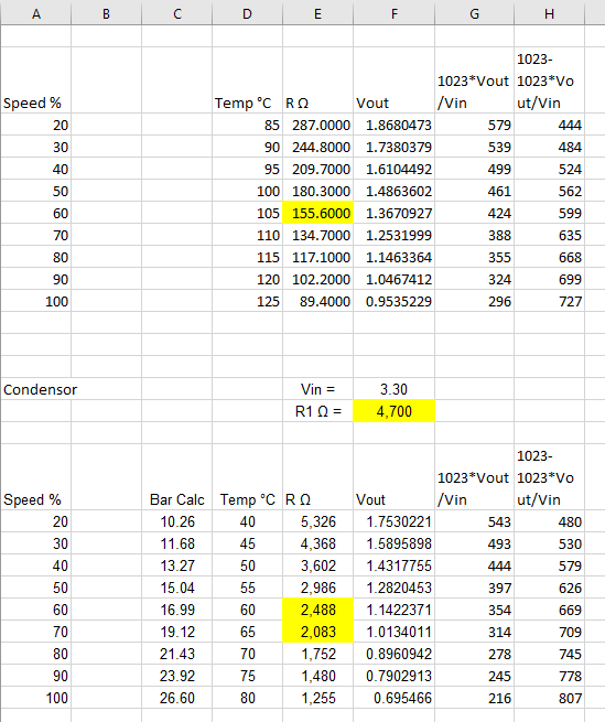
See the attached table.
Column A is the target fan speed for a given temperature. Column D and E are the temperature and resistance values for the thermisters I will be using. Column E is the voltage across the thermister calculated using voltage divider as Vout = 3.3V*R/(R1 + R). Where R = resistance from column E and R1 = the 220Ω or 4700Ω resistors depending on the sensor.
For the testing I have done R for the thermister is a 220Ω resistor representing a radiator temperature of ~ 97° C and 2200Ω for the condenser, representing condenser temperature of ~ 62° C.
As david_2018 states in post #31, I was calculating the voltage drop across the thermister and not the voltage referenced to ground. And in fact when I do measure the voltage from the pin to ground the numbers come out correct. Therfore in my program I have to use 1023-whatever I calculate across the resistor as the constants I compare to.
I still don't understand how you get a voltage from a resistor the way you showed it wired up in that diagram. Either the diagram is wrong, missing something or the laws of physics has just changed and no one told me.
And I don't understand where that table came from.
I may have the incorrect symbols in my diagram. But they are 0.1uf Non polarized ceramic capacitors.
As far as why I put them in is only because people on this form recommended it for noise suppression. I really don't understand how that works. But if you feel they are in wrong, please send me a schematic.
The thermisters are not shown in the schematic. They would go on connector JP3 across pins (13 and 14) for the condenser and across pins (15 and 16) for the radiator.
The table I made in excel from temperature and resistance data for the sensors from the manufactures of the sensors, Delphi and Littlefuse.
Your input circuits should be:

The capacitor (C1) acts like a shock absorber in a car. It resists changes in voltage. We all think of voltage signals as smooth and stable. However this is not the case. The input at the junction of R1 and TH1 will have added to the voltage you calculate, a small random voltage. The capacitor reduces this "noise" making your readings more stable.
The capacitor connects from the signal to ground of the Arduino because the Arduino ground is what the internal A/D is referenced to.
Hope this helps.
I thought you said there were no thermistors yet.
From your table you have R and R1. I can see where R1 is but I can't see the resistor R on your diagram. Is your diagram accurate for what you have now?
But on his diagram it is shown connected to the +3V3.