Hi all!
Quite some time ago I'd made a topic about my 3x3x3 and 5x5x5 LED cubes. About a year ago I started building an 8x8x8 LED cube (single color). This project was very fun and I learned very much from it. Sadly (if I remember it correctly), I never posted anything about my 8x8x8 LED cube (for those who are interested in photo's, look down further down this post). Some weeks ago I got excited to do something with my cube again. So I started thinking what I could do with my LED cube. After some browsing on the internet something struck my mind: why aren't there any opensource arduino libraries available for LED cubes that are driven by 8 bit (or higher) shift registers? The project was born :). After some research I came up with a couple of requirements:
- Library has to support a different range of LED cube sizes, from 4x4x4 all the way up to 8x8x8 (single color);
- Libray should be very easy to use, even for beginners;
- Library should contain predefined animations.
With this information I started to implement my universal LED cube library. In the upcoming paragraphs I will explain the complete library with code examples, videos, drawings, etc. I'll hope some of you will enjoy reading it :)!.
HARDWARE CONFIGURATION (important!)
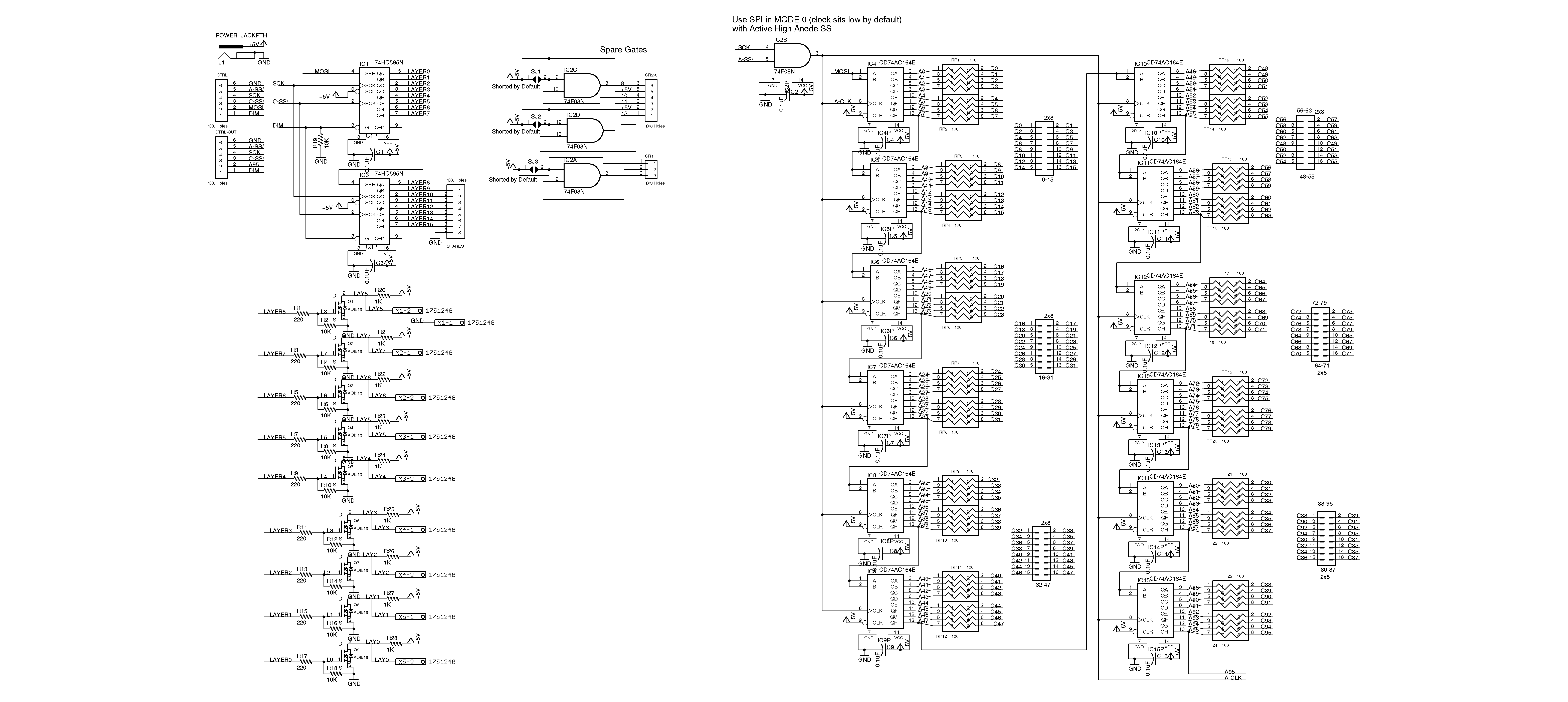
Hardware may not be the first thing you would think about with implementing a software library. But for this library it is quite crucial to define a standard hardware configuration to be able to satisfy the support for different cube sizes. So earlier on I mentioned (larger) LED cubes are usually controlled by Serial In Parallel Out shift registers. With this in mind I defined the hardware configuration that must be met in order to use the library. In the image below I made an example of a 5x5x5 LED cube (single layer in the picture) how the shift registers should be wired to the LEDs. With the image the hardware configuration can be defined as follows:
- Number of shift registers needed = (number of columns / number of output of the shift register) + 1
- The First shift register has to be the SR that is wired to the layer (connected to FETs/transitors) selector. This one is also connected via the SPI pins to the arduino microcontroller. If you put this shift register anywhere different you have to modify the sequence how the bytes are transferred to the registers.
- The column selector shift registers are cascaded with each other (+ cascaded with the layer selector). The shift register outputs are filled with a row of LEDs, whenever you have left over outputs on the shift registers, just wire the next part of the row of LEDs to the left over pins on the shift register. If that shift register becomes full then take the next cascaded one and continue wiring the left over LEDs of that row to that new shift register. Do this until all the rows are connected (in the image that means 5 times 5 rows wired to 4 shift registers in total.
- The MOSI line only connects to the first shift register (the layer selector), all the other lines (SCLK, CLEAR and LATCH) are connected parallel to the microcontroller. NOTE: SCLK and MOSI lines are predefined pins on the microcontroller, CLEAR and latch can be any pin of the microcontroller.
Do note that this schematic is far from complete, this is only used as illustration how the shift registers should be connected to the LEDs.
LIBRARY IN DETAIL
In this paragraph I will try to explain the complete library. The library itself contains multiple files, the two most important ones are the LedCube.h and LedCube.cpp. The header file contains all the definitions of the members that are used in the .cpp file. Relevant members are briefly explained in the table below.
CONSTRUCTOR
LedCube::LedCube(uint8_t latchPin, uint8_t clearPin, uint8_t cubeSize, uint16_t refreshFrequency)
{
  // Set variables
  _latchPin = latchPin;
  _clearPin = clearPin;
  _cubeSize = cubeSize;
  _layerSize = VOXELMAPPING_ARR_LAYER_SIZE;
  _zPositionCounter = 0;
  _allocated = false;
  if (refreshFrequency != 0)
    _refreshFrequency = refreshFrequency;
  else
    _refreshFrequency = 1;

  // Set pins
  pinModeFast(_latchPin, OUTPUT);
  pinModeFast(_clearPin, OUTPUT);
}
When a new instance of the class is made the constructor is called. The table showed us already that the constructor accepts 4 parameters. The first parameter should contain the microcontroller its pin number where the latches of the shift register are connected on. The second parameter should again be a pin number of the microcontroller where all the output enables of the shift register are connected on. The third parameter defines the size of the LED cube, I defined a couple of literals (see header file) to use for this parameter. The fourth and last parameter is used to define the refresh frequency of the cube (in Hz). In the constructor code below we can see the use of pinModeFast() (and later on digitalWriteFast()). This function is used instead of the normal pinMode() (and digitalWriteFast()) function to improve the overall speed of the code. This pinModeFast function is defined in a separate library (not mine) which I included in my own library, so no additional download is required.
BEGIN
// Start displaying animations on the cube
void LedCube::begin(void)
{
  _objPtr = this; // Reference pointer to current instance
  allocateVoxelMapping();
  SPI.setBitOrder(MSBFIRST);
  SPI.setDataMode(SPI_MODE0);
  SPI.setClockDivider(SPI_CLOCK_DIV2); // Fastest data transfer
  SPI.begin();
  initInterrupt();
}
To start refreshing the LED cube you simply call the function begin(). This function initializes the SPI, timer and voxel mapping arrays. SPI is configured as follows:
- Bit order: MSB first
- Data mode: SPI_MODE0
- Clock divider: SPI_CLOCK_DIV2
Gamma correction table generator (files).zip (13 KB)
LedCube(old V3.0).zip (19.6 KB)
LedCube.zip (60.5 KB)