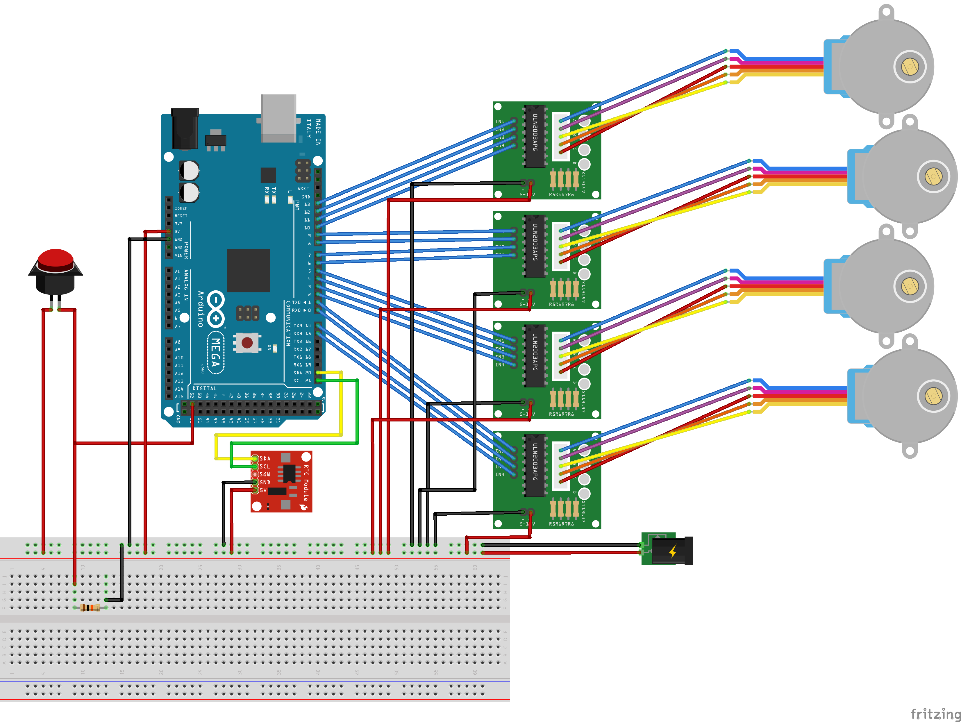
My project consists of controlling 4x 28BYJ-48 motors (via ULN2003 drivers). In addition to this I have a real time clock module and some miscellaneous parts like switches and maybe one or two LEDs. (I'm basically making an Arduino powered clock).
The motors will be driving some gears, but all of the gears have little to no resistance as they are on bearings and loads are very light. I'll also only be turning the motors one at a time. So I believe the current demand will be fairly low as a result.
Ideally I would like to avoid batteries as the power source as they're a pain to have to keep remembering to charge or they're flat when I need them (+ they're kind of expensive if you want long lasting lipo ones).
So I was hoping to use a 5V 2A power supply (i.e. phone/tablet charger) and was hoping if someone could advise if this is adequate for the job.
The RTC module (DS3232) I believe draws 300mA max, the Arduino I belive has a max draw of 200mA and the LEDs (4x) should only draw 80mA so I was wondering if the remaining 1.4A is enough for the motors and Arduino?
Fritzing image attached to hopefully clarify the layout.
So I believe the current demand will be fairly low as a result.
The current requirement for a stepper has less to do with the load it needs to move than with its need to hold still between moves. All 4 steppers need to hold still. 2A may not be enough. In terms of amperage, you can ignore the Arduino and LEDs.
You'll probably be OK. What's the current rating on the motor?
but all of the gears have little to no resistance as they are on bearings and loads are very light. I'll also only be turning the motors one at a time. So I believe the current demand will be fairly low as a result.
Stepper motors are a little "weird" that way, and current isn't always s directly related to load or torque.
In general with motors, you have to assume that you're going to get "worst case" (maximum) current at some point (although you don't have to assume all motors will run at once).
It says it's a 5V 4A supply for LEDs, but was hoping this would be enough. Not sure if I would keep the jack or clip off the end and replace it without something else (i.e. XT-60 connector).
DVDdoug:
You'll probably be OK. What's the current rating on the motor?
Afraid I couldn't find this listed anywhere. It's a 28BYJ-48. Below are two datasheets I found but every one of them I look at seems to not list a max current.
jremington:
Measure the current required by the motors, using a multimeter. They are by far the biggest draw.
Any chance of a quick crash course in measuring current through a multimeter. I couldn't seem to do this as I would measure voltage. I think I read somewhere I need to "break" the power line and have it run through the multimeter (as it's part of the wire connection) instead of the multimeter probing two contact points. Is that correct?
To measure amp draw, the meter needs to be in series, so yes, break the circuit and recomplete it through the meter after you've put it on the correct setting.
Below are two datasheets I found but every one of them I look at seems to not list a max current.
Yes it does. It gives you the voltage and the coil resistance. Use ohms law to find the current.
If you have tried to measure current the way you measure voltage then you have blown the input fuse of your meter so it needs replacing first. Yes you need to make the current pass through your meter.
To measure amp draw, the meter needs to be in series, so yes, break the circuit and recomplete it through the meter after you've put it on the correct setting.
Thanks, will check this out tomorrow and report back.
Grumpy_Mike:
Yes it does. It gives you the voltage and the coil resistance. Use ohms law to find the current.
If you have tried to measure current the way you measure voltage then you have blown the input fuse of your meter so it needs replacing first. Yes you need to make the current pass through your meter.
Thanks, think I was searching for it just being listed as "max current".
So if I worked it out right (and if I'm reading the robocraft datasheet correctly. Ignore the rapsberrypi-spy link, I accidentally linked the 12v version and am using the 5V ones ....), it has 5V and 50 ohms resistance.
So the current is 0.1A, is that correct?
[Trying to learn, so asking Sensei to check my homework :P]
It does say 4 phases on the datasheet, so I'm not sure if the DC resistance applies to the motor as a whole or if it applies to each phase (so that would be 50 ohms x 4 = 200, making the current 0.02 ... which sounds too low)
Haven't tried using the multimeter yet, was asking for advice to avoid the undesireable situations like the one you just mentioned as I'm still trying to get my head around the hardware side of things