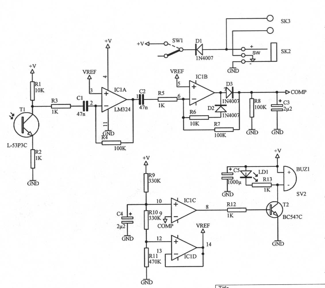
I'm terribly ashamed of myself, but I just can't seem to figure out how to hook up the 0 to around 2,5 volt result from a Velleman IR gate kit (coming from from LD1 on the receiver, as the BUZ is 9v, see http://www.velleman.be/downloads/files/schema/receiver.jpg) to the analog inputs.
The 2,5V to A1 and ground to ground: doesnt work
Vice versa: doesnt work
I understand I need some sort of reference/ground connection as just the 2,5V into the A1 doesn't do anything (getting gibberish results)
It seems like such a simple problem, but my head is too messy and I just cant figure it out. (so hear my outcry: help!)
Connecting the analog output to the analog input pin will only work if you have an analog output voltage that is positive, that is, 0V to +5V.
I don't understand why you've written +/- 2.5V, since that circuit will produce a 0-9V signal, given a 9V battery.
To debug your problem, can you connect a potentiometer from +5V to ground, and then connect the wiper to the analog input? That way, we could see whether the trouble is in the hardware or the software. Could you also post your Sketch code?
Ultimately, you'll need a level-shifting amplifier of some sort to interface a +/- 2.5V analog signal. (If that's what you meant?)
If you want to connect the output of that Velleman circuit to the Arduino, surely the simplest way would be to use a digital input, because the signal is either on or off, yes? So you could take a signal from pin 8 of IC1C and drop it down to 0-5V with some resistors.
Hi, thanks for replying! I meant to say (and altered the text) that it reaches from 0 to around +2,5V, so all voltages are positive to start with.
Debugging can only be done tomorrow morning, as I'm not on the location where I'm working at. The problem is it really really needs to work tomorrow, and as this seems such a small little problem I figured someone (like you) could come up with a connect the red to the 0 and then cut the green wire so the bomb won't explode-like solution
But what you are saying is that the 2V will be regarded as HIGH by the digital input? I can't believe I havent tried that yet, I had the assumption* you need 5V for that. But wouldn't I not need some sort of reference wire somewhere in a setup like this?
Do you just want to see when the LED is on? If so that is a digital signal. connect the collector of T2 through a 1K resistor to the input pin of the arduino, and another from the input pin to ground. Connect the ground of this circuit to the ground of the arduino. When the LED is on you will read zero on the input, when it is off you will read one.
hey guys, i just wanted to thank you for the answers I've been given here. I agreed with the idea from grumpy_mike but for some reason the entire Velleman kit crashed when I tried to hook it up that way (constant leds on etc, untill the kit is unplugged). So the only way (in theory) would still be using a triac of some sort I guess.
However, as this part of the project was cancelled by the director I haven't looked into it any more after this. Next time I'll also make sure to just use something like the ping))) sensor. If they don't call me into the project 2 days before deadline again that is..