Virtual, variable resistors, with saved presets recallable by MIDI

allanhurst:
No big deal - just another wire.....

Right, but the MCP41100 (single POT version) doesn't have an SO pin. I read through the datasheet a few times, and the MCP42xxx version (dual POTs) has an SO pin, but the datasheet only mentions it for daisy chaining devices together. My MCP41100's will be here this week.

Maybe the Ack comes back through the SI pin?

MCP41100 Datasheet

I think I'll use the parts I ordered to do my learning and testing, but have been looking into getting some 10 bit resolution POTs for the final implementation. I understand this makes it challenging due to the difference in message lengths, and the Mega328's 8bit message length (so there's a need to send three messages instead of two, meaning one command message and two data messages), but the analog POT will be read with values of 0-1023, so for optimal control over the parameters in the pedal, I think I'll want to utilize that level of resolution forn the values being sent back to the DigiPOTs.

Still learning and planning ... Hope to be testing soon

No - it's serial out for the next device in the daisy chain

Allan

So where does MISO happen then?

for this device you don't need it. I hadn't looked up it's spec before my previous reply.....

Allan

No problem at all, I really appreciate your help. I feel like I accomplished something today!

For a test of my understanding, I setup a flashing LED, with speed of the flash controlled by a Potentiometer (POT1). Simple enough.

Then I added a second potentiometer (POT2) to act as a memory location selection device (0 - 99), and added 2 buttons. Button1 for storing the value, and button 2 for recalling.

So, when turning POT1, the speed of the flashing changes accordingly. Then turning POT2 allows selection of a number from 0 -99 (using a divider and the (round) command). Pressing Button 1 stores the value into an array using POT2's value (after normalizing it into the 0 - 99 scale) as the location. Button 1 recalls the stored value from the array, and sets the LED flashing at whatever value it retrieved.

Then the LED stays flashing at the recalled rate until POT1 is moved (then it goes to real time) or until another preset is recalled.

Again, I truly appreciate all the help and input you've given me. If you see anything I did wrong, or just inefficient, I'm open to learning more!

I'm still awaiting the DigiPOTs to be delivered so I can get to experimenting with SPI.

Here is the board and connections:

And here is the code:

    // Pin Selects
int potvalPin = 3;    // select the input pin for value potentiometer
int potpresetPin = 1;   // select input pin for preset control potentiometer
int ledPin = 2;   // select output pin for the LED
int setPin = 7;  // Select input pin for button to set a preset
int recallPin = 5;   // select input pin for button to recall a preset

    // Variable Definition
int setbutton = 0;  // variable to store state of the preset set button
int recallbutton = 0;  // variable to store the state of the preset recall button
int potstoredval = 0; // variable to store the "value potentiometer" previous value for comparison
int potreadval = 0;       // variable to store the real time value from value potentiometer
int actualvalue = 0;  //  variable to store the current value
int preset = 0;     // variable to store preset number from preset potentiometer 

    //Array Definition 
int myPresets[100];   // create array to store presets

    // Initialize
void setup() {
  pinMode(ledPin, OUTPUT);  // declare the ledPin as an OUTPUT
  pinMode(setPin, INPUT);  // declare the presetsetPin as an INPUT
  pinMode(recallPin, INPUT);  // declare the presetrecallPin as an INPUT
  potreadval = 1023 - analogRead(potvalPin);  // read current value from the value pot
  actualvalue = potreadval;  // set current value to pot read value
  Serial.begin(9600);  // establish serial communication for monitoring
}

    //Main Code
void loop() {
  potreadval = 1023 - analogRead(potvalPin);  // read the value POT's real time position and store it
  setbutton = digitalRead(setPin);  // Read the set button's state
  recallbutton = digitalRead(recallPin);  //  read the recall button's state
  if(potreadval != potstoredval) RealTime();  // if the value POT has been turned, go into real time mode
  if (setbutton == HIGH) SetPreset();  //  if the SET button is pressed, go to subroutine to store the preset
  if (recallbutton == HIGH) RecallPreset();  //  if the RECALL button is pressed, go to subroutine to recall the value

  digitalWrite(ledPin, HIGH);  // turn the ledPin on
  delay(actualvalue);                  // stop the program for some time
  digitalWrite(ledPin, LOW);   // turn the ledPin off
  delay(actualvalue);                  // stop the program for some time
  
  Serial.print ("Actual Value (flashing) = ");
  Serial.println (actualvalue);
  Serial.print ("Pot Read Value = ");
  Serial.println (potreadval);
  Serial.print ("Pot Stored Value = ");
  Serial.println (potstoredval);
}

    // Realtime Mode
void RealTime() {
  Serial.println ("Start RealTime Subroutine");
  potreadval = 1023 - analogRead(potvalPin);    // read the value from the sensor
  actualvalue = potreadval;  // set flashing speed
  potstoredval = actualvalue;  // set previous value
}

    // Store Preset Mode
void SetPreset() {
  Serial.println ("Start SetPreset Subroutine");
  preset = round(analogRead(potpresetPin)/10.32);  // read preset POT position, and determine which preset between 0 - 99 it cooresponds to
  potreadval = 1023 - analogRead(potvalPin);  // read the value POT
  myPresets[preset] = potreadval;  // write the value of the value POT to the array, in the position of the value of the preset POT  
}

    // Recall Preset Mode
void RecallPreset() {
  Serial.println ("Start RecallPreset Subroutine");
  preset = round(analogRead(potpresetPin)/10.32);  // read preset POT position, and determine which preset between 0 - 99 it cooresponds to
  actualvalue = myPresets[preset];  //  set flashing value to the recalled value
}


Pins in holes is going to give you flaky connections sooner or later (and sooner rather than later).
I'd suggest soldering in some male pins (extending down) so you can plug the ProMini clone into a breadboard, or solder in some female pins (from the top) that you can more securely plug wires into the header.
Or long tail female pins so you can both.
Couple of these on each set of pins, sand the mating faces so they sit nice & flush next to each other.
http://www.ebay.com/itm/10x-8-Pin-Female-Tall-Stackable-Header-Connector-Socket-for-Arduino-Shield-8P-/131704730537?hash=item1eaa36b3a9:g:jkAAAOSwqYBWnTbm

I see you're using delay() for timing - that's OK for a simple hack, but may give you problems when you start to add such features as the MIDI interface.

Check out the 'Blink without delay' example in the IDE for a better approach

Allan

CrossRoads:
Pins in holes is going to give you flaky connections sooner or later (and sooner rather than later).

Most certainly the way I have them connected now will cause an issue if I left it like that long term. I'll end up soldering it down after I've determine a mounting strategy for the board inside the effect pedal. For now, this is just simple testing.

allanhurst:
I see you're using delay() for timing - that's OK for a simple hack, but may give you problems when you start to add such features as the MIDI interface.

Check out the 'Blink without delay' example in the IDE for a better approach

I was thinking about this last night, due to the delay approach causing the "value POT" to be unresponsive and laggy when longer delays are set. I wondered if using # of clock cycles would work, but the time differential strategy in the "Blink without delay" IDE example looks to be a good way to do it.

Then the POT could be sensitive and change the timing even if the previously set interval hasn't elapsed yet.

Of course, the final purpose won't be timed event like this, but it's a good learning experience for me non-the-less.

Just a quick note:

When I updated the code to not use the "delay" command, it worked, although the "RealTime" subroutine was being triggered constantly. At first I though it was related to the change from "delay" to time interval, but then figured out it was due to the analog pot being read having variance in the reading. So the reading of the POT was floating around, sometimes even by less than 1, causing erratic behavior.

I resolved it by putting a variance of +/- 2 in the comparison, but not sure if this is the right way to solve for this.

  if(potstoredval+2 <= potreadval || potstoredval-2 >= potreadval) RealTime();

where "potstoredval" = stored previous reading from the POT
"potreadval" = current reading from the POT
"RealTime" = subroutine/function to update the flashing speed

Does this variance of +/- 2 seem like good practice for components that may have some variance like this?

Stoopalini:
So where does MISO happen then?

You only need that when you want to get information back from an SPI device. In the case of a digital pot their is nothing to read.

Grumpy_Mike:
You only need that when you want to get information back from an SPI device. In the case of a digital pot their is nothing to read.

Perfect, thanks.

Here's my next challenge: Getting the preset stored values to retain when power is removed from the Arduino. I see I can use the EEPROM, but only for 100,000 writes. I'd like the pedal to be usable for years to come, and there's no telling how many times I'll update the preset values.

Does this mean FRAM is really the only option for me here? Or is there a way to prevent the initialization routine from clearing out the memory blocks where the array is being stored? ... and if so, I assume that means I need to define the memory location for the array to be stored within?

I don't think you'll run out of 100,000 writes in your lifetime. Especially if you only rewrite when there's a change

And since the data you want to store is probably only a few bytes, use say 50,000 writes in the first 100 bytes , then the next, and so on

Allan

Ok, that makes sense.

Maybe I'm not understanding the 100k write limitation. Is the limitation that you can only initiate a write command to the EEPROM 100k times, regardless of how much data or what blocks you are storing it in? Or is the limitation related to each memory address only able to be written to 100k times each.

So if I have an array of 100 values, and I change array item #5 100k times, does it mean I can no longer write to that particular memory address but I can still write to others; or does it mean I can no longer write to any memory address within the EEPROM?

Made a little more progress on the logic.

I changed the flashing logic to use cycles. Trying to get it to work with time based was proving problematic, so I just used a simple counter. It seems to work well, although not sure how it'll change when there's more code for the program to cycle through.

I changed Button 1 to be dual function, where a short press recalls the a preset determined by the position of POT2, and a long press stores the value of POT1 to a preset determined by position of POT2.

I repurposed button 2 to dump the array values onto the screen through Serial.print, so I can validate things are working.

Making the dual function button was a neat exercise. I was able to program it where each command is only executed once, instead of multiple times while the button(s) are pressed. This was me thinking ahead to minimize the writes to EEPROM when I move the array into that space. Seems to work well coded like this, but of course, I'm open to suggestions for improvement.

I also changed the way things appear on the Serial Monitor, so I can make sense of what's happening.

I tried to post the new code, but apparently it's too long for the forum limitation on characters per post. IF interested, see it attached.

POT_n_LED_Test.ino (8.05 KB)

So if I have an array of 100 values, and I change array item #5 100k times, does it mean I can no longer write to that particular memory address but I can still write to others;

Yes, in fact that 100K is just the minimum number that is guaranteed.

So suppose you save a variable 10 times a day every day. Then 100K will give you 27 years of operation.

Makes sense, thanks! So EEPROM storage for the array it is.

I made some more progress lately. I now have 2 potentiometers hooked up, to simulate the LEVEL and DRIVE POTs in the effects pedal, and two LEDs to stand-in for the DigiPots, which haven't arrived yet (due in on Monday). I also removed the preset selection POT and button and replaced both with a rotary encoder with integrated button.

The functionality works by using the two POTs to change the values, then rotate the rotary encoder to select a preset number from 0 -99, and do a long press on the encoder's button. That saves both POT values to the preset # in two arrays (one for each POT).

For recalling presets, you rotate the rotary encoder to a preset # and short press the encoder button.

After recalling, if you move one of the knobs, the value changes of just that one POT, but not the other. I did this thinking through the use case, where I'm playing guitar, and I recalled a preset ... but maybe the drive is just a bit too much, or the level needs to come up a bit. I can adjust just one knob, then re-save the preset without having to redial in the other knob.

I'm building a small breakout box which has the rotary encoder, and will also house a 2 digit, 7-segment display for displaying the preset # being selected by the rotary encoder. The breakout box will connect to the pedal through some kind of interconnect ... maybe a CAT6e cable? not sure yet.

I'm hoping I can use the USB port on the Nano for the midi input, so the pedal will be able to function even without the breakout box attached. It will certainly work normally, by manually turning the knobs, but I'd like it to be able to do MIDI recall even without the breakout box connected. Still need to research that piece.

Here is what the proto looks like today. The micro button on the left is just for debugging. It dumps the array values on the screen through Serial.print ().

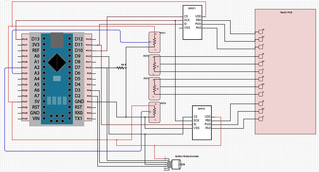
Here is the current version of my diagram. Of course, the LEDs are standing in for the Digi-POTS, and I haven't drawn the display or the MIDI interface in yet either. Like stated above though, I'm hoping I can use a USB to MIDI cable direct into the USB port on the Nano. The segment displays will hopefully arrive next week.

And the code is attached, if anyone is interested.

POT_n_LED_Test.ino (13.5 KB)

I'm hoping I can use the USB port on the Nano for the midi input,

I'm hoping I can use a USB to MIDI cable direct into the USB port on the Nano.

A USB to MIDI cable has MIDI 5 pin DIN sockets and so will not fit into a Nano. Even if it did fit it would not work. A Nano ( or any other Arduino ) expects, unsurprisingly, USB protocol on the USB socket.

Do you know the difference between USB host and USB client?

Your computer is a host and the Arduino a client. Something like a MIDI keyboard with a USB connector on it is a client. You can not connect USB clients together, you can only connect a client to a host. The different connectors on each end of a USB cable are designed to prevent you plugging two hosts or two clients together.

Grumpy_Mike:
A USB to MIDI cable has MIDI 5 pin DIN sockets and so will not fit into a Nano. Even if it did fit it would not work. A Nano ( or any other Arduino ) expects, unsurprisingly, USB protocol on the USB socket.

It was my understanding the MIDI protocol was actually just serial protocol, and could be read through the Serial bus of the Arduino. and since the default serial 0 bus is tied to the USB port, I was hoping it would work there. If not, I'll need another solution. Maybe a second Arduino inside the breakout box, communicating through serial to the Nano inside the pedal, is a better design?

Grumpy_Mike:
Do you know the difference between USB host and USB client?

Yes, I understand the difference.

I have an iConnectAudio4+ device acting as a central hub on my pedalboard, in which all the MIDI devices I use are connected through either 5 pin DIN, USB host jack, or USB client jacks. Depending on the need, this can be 3-4 five pin DIN MIDI devices, as well as 2-3 USB host and client devices. They're all sharing a common MIDI network.

Then I have a MIDI foot controller connected to the host jack on the iConnectAudio4+, acting as a central controller for patch controls. The foot controller sends a sequence of commands out to the iConnect device, which in turn routs them to the appropriate devices through 5 pin DIN MIDI, or USB, or both.

In your MIDI keyboard example, it may be connected to a physical USB client type jack, but is acting as a MIDI host, sending MIDI control data to some MIDI device or software.

That said, MIDI devices connected through a USB host or a USB client type jack can send and receive MIDI commands in a MIDI network; although I only need the pedal to receive in this case.

The Arduino could easily be plugged into my iConnect device to become an additional MIDI device on the existing MIDI network, if the USB port could be used to bring MIDI serial data in. I just don't know if the Arduino can be coded to read MIDI commands through the onboard USB port. I would think it could, considering it's tied to Serial 0.

Or, maybe I think I understand it and I'm really confused??

It looks like the MidiUSB.read() function from the MIDIUSB library does exactly what I'm looking for ... Read midi info from the USB port.

Am I misunderstanding something here?

It was my understanding the MIDI protocol was actually just serial protocol, and could be read through the Serial bus of the Arduino.

Yes it can, but the computer sending it normally thinks it is sending to a MIDI HID not a serial port. Sometimes you can have a helper application inside the computer to do this conversion. A good one is called hairless.