BTW MOSFETs in an H-bridge connected to big 12V or 24V batteries don't fry if
subject to shoot-through, they explode generating shrapnel, so use eye-protection
when working with high-current supplies.
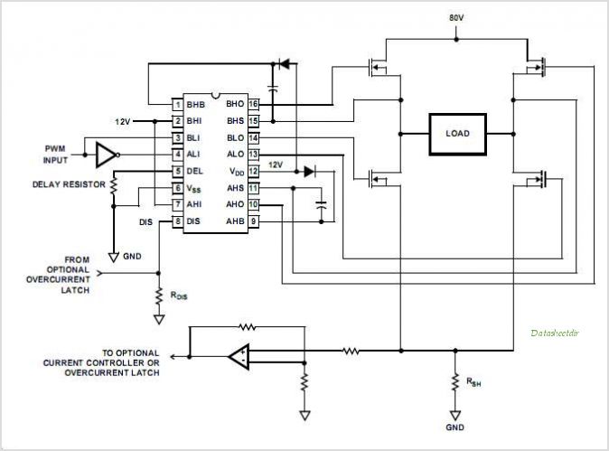
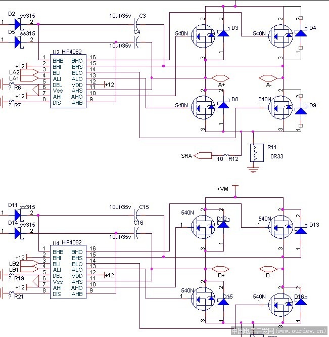
I missed the part where you said it was a school project. There are H-Bridge driver chips available that can manage the "shoot-through" for you. They also use a charge pump to generate the high-side gate drive, so you can use all N-Channel FET's. Also it won't let you turn both FETs on in the same leg.
Using this chip makes the task more reasonable since it has adjustable shoot-through time delays built into it. If you stay with the Arduino's 400Hz PWM you shouldn't have much trouble. If you raise the PWM to 10kHz or so, the storage times of those parasitic diodes in the FETs will generate a current spike that will show itself as a lot of power dissipation.
I doubt the charge pump in the 4082 will have enough current to drive the top-side bases. It's pretty much designed to run FETs. Those transistors you've chosen are going to dissipate a bit of power since their "ON" spec is 2V at best. Means they will get 7W worth of heat.
Yeah, he still wants to run at 24V! Are you stuck on 12 for some reason? Also it's a pretty lame design since you have no way to PWM the bridge or allow any delay for shoot-through. If I was his professor, I would give him a "D" for that design.
rmetzner49:
Yeah, he still wants to run at 24V! Are you stuck on 12 for some reason? Also it's a pretty lame design since you have no way to PWM the bridge or allow any delay for shoot-through. If I was his professor, I would give him a "D" for that design.
Then what type of circuit would you recommend? I have to use the BDV66B and BVD67B.
Before you get all bent out of shape, the circuit I posted is just a basic template. The devices I recommended can handle 60V but I don't have any CAD sw to make a schematic and rather than hand draw one I just posted that one . Ignore the 12V and pretend it says 24V . Is that so hard to do. (also , subsitute the part numbers I recommended.
If we asked that question on every Newbie post we'd never get anywhere..... XD @metzner49
I have a question. What's with "shoot -through" comments ?
If you're going to complain that a schematic (circuit design) doesn't have "shoot-through delay protection" doesn't it make sense to post a schematic that illustrates that feature so the rest of the readers know what your talking about. Otherwise you are having a one way conversation , citing concepts that nobody else is familiar with. If you are not going to explain this feature with a schematic , then don't bring up the subject because you are alone in your conversation.,
Otherwise you are having a one way conversation , citing concepts that nobody else is familiar with. If you are not going to explain this feature with a schematic , then don't bring up the subject because you are alone in your conversation.,
@Raschemmel: I doubt I am having a one way conversation. As I've said from the start, a newbie has no business attempting to design an H-Bridge. I'm sure anyone that's ever designed an H-Bridge and attempted to run same above 15Khz understands "shoot through". It's also called "cross conduction". Please Google it and understand it before your feeble attempt to SLAM me. The fact that you don't and aren't willing to research it yourself causes me no loss of sleep. Your previous comments that don't consider the OP's request for 24V and Bipolar transistors make me wonder who is even silly enough to follow your advice that you just copied from another web site anyway.
Point-1: Newbie has no business designing H- Bridge.
CONCEDE (There is no argument
that makes any sense.
Point-2: I have no business critcizing your comment if I haven' t even researched it.
FAIR ENOUGH. I'll give you thst.
Point-3: You should link example oc "shoot-through" if you are going to bring it up.
I looked at your link but didn't see any mention of that. Can you link that pAge or post a quote?
RE: Power Supply Voltage and 4011.
Ha ha ha. Like you didn't know I meant the Motor Supply and NOT the CMOS logic supply. You know very well those cmos chips will work with a 5V TTL signal from an arduino output. You can change the logic supply voltage to 5 V.
Oh, that was good.
I thought I could post that without laughing, but I could not.
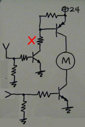
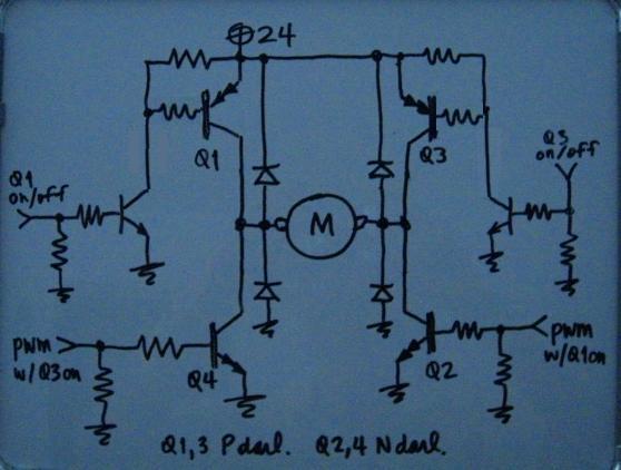
Well, here's the rest of the circuit.
It's rudimentary for sure.
Shoot-through and other concerns can be addressed in software (no slamming from FWD to REV, no having FWD Hi and REV pwm going at the same time, stuff like that.)
"newbie" isn't designing, he's trawling for others to do that, like it's a piece of cake. Well, that's all for me till Jimmy Doce starts par-ti-ci-pa-ting.
changed the placement of the darlingtons' base resistors (better now.)
Then what type of circuit would you recommend? I have to use the BDV66B and BVD67B.
@Jimmy12 Is this because you already purchased them? Or did your instructor say to use Bipolars?
Using FETs gives you absolutely the most efficient bridge. The transistors you've chosen come with a penalty: They will at best give you a 2V drop since they are Darlingtons. Since you have two on at any given time, you are hit with a (4V * 3.5A) or 14 Watt penalty right off the bat, and you haven't added switching losses.
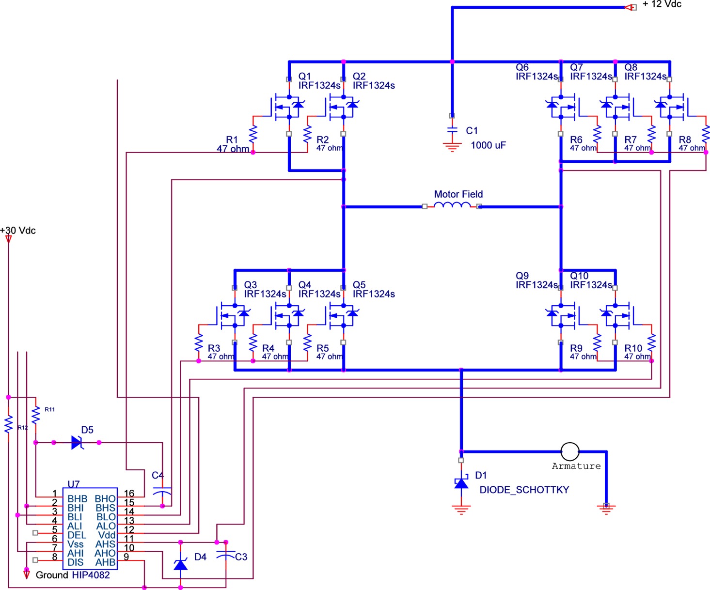
Also, the parts count goes WAY up. If you use FETs, there is a cookbook solution with really low parts count that has the "cross conduction" protection built into it and also a delay timer to prevent "shoot through". All you do is give the IC logic inputs such as from an Arduino and away you go. The part is an Intersil HIP4082 and has the reference design in the data sheet. FETs are relatively cheap, you can buy 5 pcs. RFP50N06 on E-bay for $4.99. With that device's 22 milliohm RDSon your power will be
(.022 * 3.5A * 2) or 0.154 watts because you have two on at once. Of course there are switching losses but those are also less with an FET than a bipolar. Just my suggestion. Pancake has the start of a design that can work, but a lot is left up to you.
From Raschemmel: You can change the logic supply voltage to 5 V.
That will still let the smoke out. When Q6 is "off" and the CD4011's inputs are pulled up to 24V by the 10K connected to the motor supply. What I'm trying to instill in you (albeit unsuccessfully) is when you take someone's design and just arbitrarily jack up the supply voltage without understanding the impact you will make smoke.
@Raschemmel: Of those designs you linked, several had additional diodes across the FET in the same direction as the built-in parasitic diode in the FET. Do you know why they would do this?