Put the photos inline here!
Me, and others aren’t going offsite to help you - sorry.
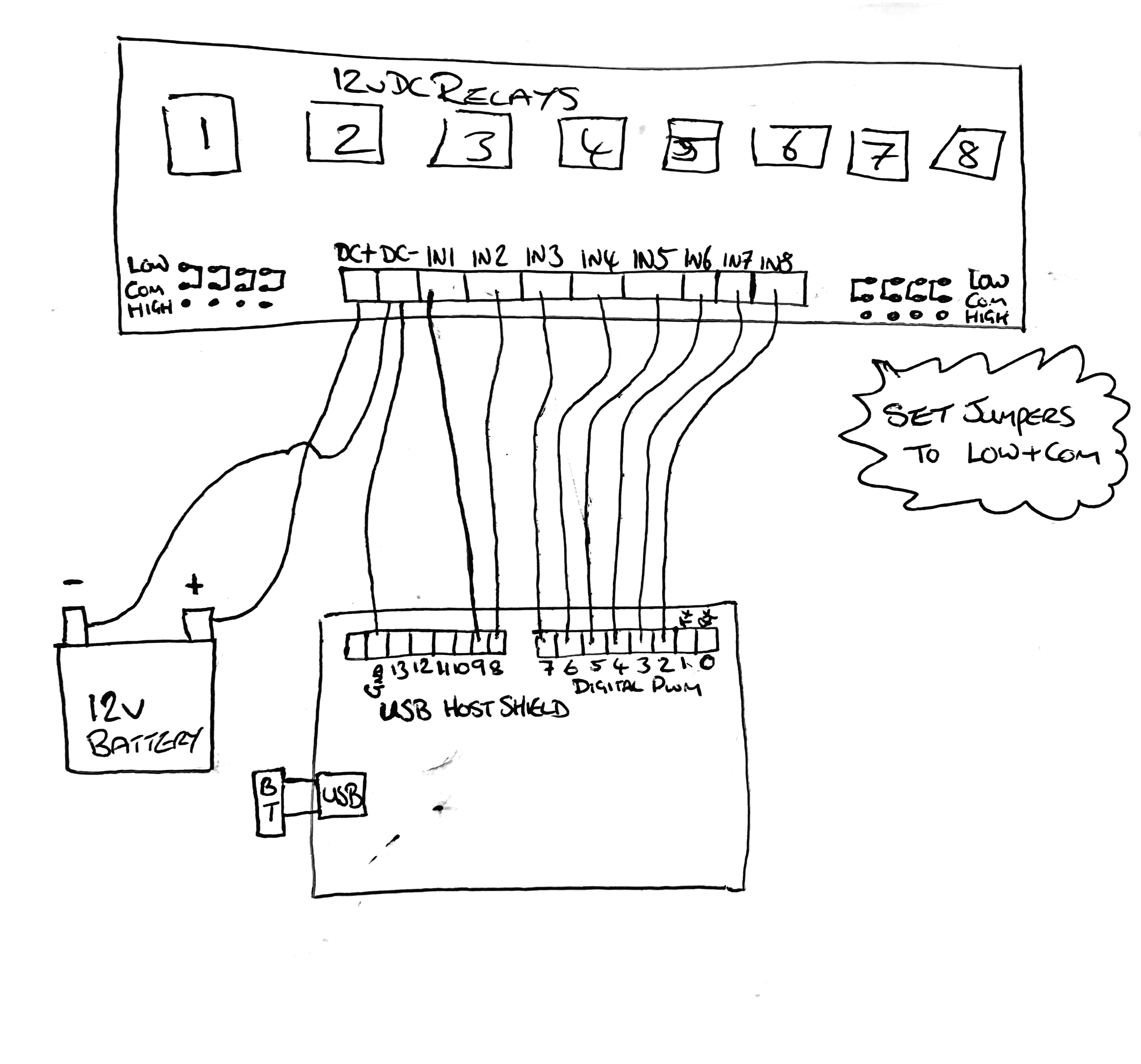
Is it similar to this?


If so, you probably connect +12v to DC+ and the negative of that 12 power supply to DC- .
DC- also to ARDUINO GND.
Still need a schematic of this relay board.
Larryd yes exactly that board.
Thank you I shall test the ground to arduino too and see what happens.
Lastchancename I would however when I upload and choose small or medium to keep total photos under 2mb it says error so I gave up
Many thanks all
I shall update this tomorrow when I’ve tested that way out
images: ok, but keep trying for the future
You’ll figure a way to do it.
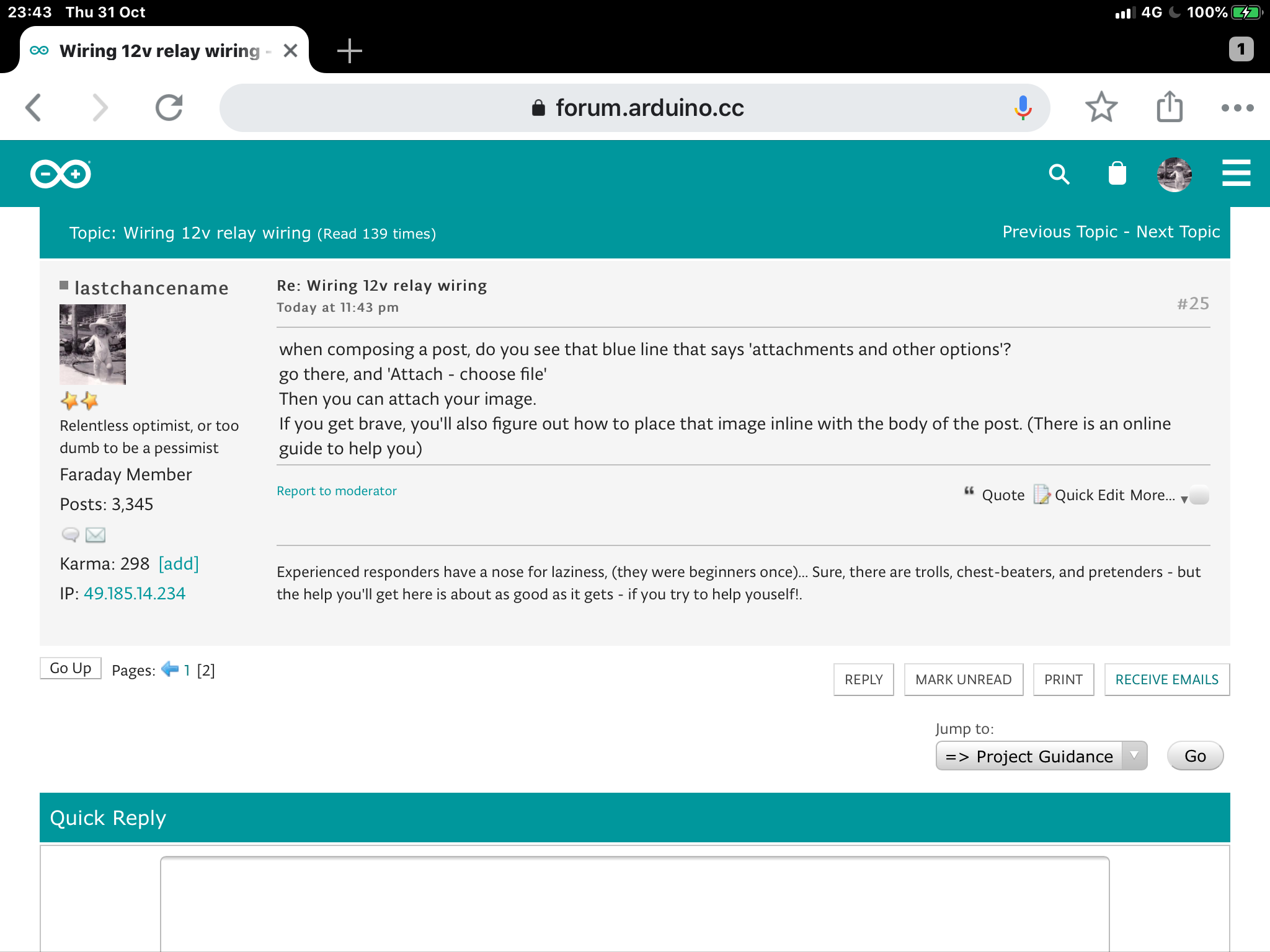
when composing a post, do you see that blue line that says ‘attachments and other options’?
go there, and ‘Attach - choose file’
Then you can attach your image.
If you get brave, you’ll also figure out how to place that image inline with the body of the post. (There is an online guide to help you)
like this
Lastchancename. The trouble I have is my iPhone takes photos as jpeg not jpg. The system won’t allow jpeg but allows jpg. Ive just spent the last 10 mins trying to edit the message and upload the image edited and alsorts. I’ve had to scan as document on Dropbox have it as png file then save that png and upload it. It’s now uploaded fine.
Yes perry thank you
OP, ok, that’s curious, because the screen shot above was from my iPad...!
It wasn’t a camera shot tho’ - maybe there’s a difference??
The wiring looks ok.
Now it’s connected properly, can we see your code?
inline with code tags...
// the setup function runs once when you press reset or power the board
void setup() {
  // initialize digital pin 2-9 as an output.
  pinMode(2, OUTPUT);
  pinMode(3, OUTPUT);
  pinMode(4, OUTPUT);
  pinMode(5, OUTPUT);
  pinMode(6, OUTPUT);
  pinMode(7, OUTPUT);
  pinMode(8, OUTPUT);
  pinMode(9, OUTPUT);
}

// the loop function runs over and over again forever
void loop() {
  digitalWrite(2, HIGH);   // turn the Relay on (HIGH is the voltage level)
  delay(5000);                       // wait for 5 seconds
  digitalWrite(2, LOW);   // turn the Relay on (HIGH is the voltage level)
  delay(5000);                       // wait for 5 seconds
}
this is basic so i can get one relay to switch but as soon as i connected ground from the relay board to the host shield gnd all relays activated and wont deactivate.
this sends 5v down the pin for 5 seconds then goes back to 0v.
the code i eventually plan on using is the PS3BT one.
/*
 Example sketch for the PS3 Bluetooth library - developed by Kristian Lauszus
 For more information visit my blog: http://blog.tkjelectronics.dk/ or
 send me an e-mail:  kristianl@tkjelectronics.com
 */

#include <PS3BT.h>
#include <usbhub.h>

// Satisfy the IDE, which needs to see the include statment in the ino too.
#ifdef dobogusinclude
#include <spi4teensy3.h>
#endif
#include <SPI.h>

USB Usb;
//USBHub Hub1(&Usb); // Some dongles have a hub inside

BTD Btd(&Usb); // You have to create the Bluetooth Dongle instance like so
/* You can create the instance of the class in two ways */
PS3BT PS3(&Btd); // This will just create the instance
//PS3BT PS3(&Btd, 0x00, 0x15, 0x83, 0x3D, 0x0A, 0x57); // This will also store the bluetooth address - this can be obtained from the dongle when running the sketch

bool printTemperature, printAngle;

void setup() {
  Serial.begin(115200);
#if !defined(__MIPSEL__)
  while (!Serial); // Wait for serial port to connect - used on Leonardo, Teensy and other boards with built-in USB CDC serial connection
#endif
  if (Usb.Init() == -1) {
    Serial.print(F("\r\nOSC did not start"));
    while (1); //halt
  }
  Serial.print(F("\r\nPS3 Bluetooth Library Started"));
}
void loop() {
  Usb.Task();

  if (PS3.PS3Connected || PS3.PS3NavigationConnected) {
    if (PS3.getAnalogHat(LeftHatX) > 137 || PS3.getAnalogHat(LeftHatX) < 117 || PS3.getAnalogHat(LeftHatY) > 137 || PS3.getAnalogHat(LeftHatY) < 117 || PS3.getAnalogHat(RightHatX) > 137 || PS3.getAnalogHat(RightHatX) < 117 || PS3.getAnalogHat(RightHatY) > 137 || PS3.getAnalogHat(RightHatY) < 117) {
      Serial.print(F("\r\nLeftHatX: "));
      Serial.print(PS3.getAnalogHat(LeftHatX));
      Serial.print(F("\tLeftHatY: "));
      Serial.print(PS3.getAnalogHat(LeftHatY));
      if (PS3.PS3Connected) { // The Navigation controller only have one joystick
        Serial.print(F("\tRightHatX: "));
        Serial.print(PS3.getAnalogHat(RightHatX));
        Serial.print(F("\tRightHatY: "));
        Serial.print(PS3.getAnalogHat(RightHatY));
      }
    }

    // Analog button values can be read from almost all buttons
    if (PS3.getAnalogButton(L2) || PS3.getAnalogButton(R2)) {
      Serial.print(F("\r\nL2: "));
      Serial.print(PS3.getAnalogButton(L2));
      if (PS3.PS3Connected) {
        Serial.print(F("\tR2: "));
        Serial.print(PS3.getAnalogButton(R2));
      }
    }

    if (PS3.getButtonClick(PS)) {
      Serial.print(F("\r\nPS"));
      PS3.disconnect();
    }
    else {
      if (PS3.getButtonClick(TRIANGLE)) {
        Serial.print(F("\r\nTriangle"));
        PS3.setRumbleOn(RumbleLow);
      }
      if (PS3.getButtonClick(CIRCLE)) {
        Serial.print(F("\r\nCircle"));
        PS3.setRumbleOn(RumbleHigh);
      }
      if (PS3.getButtonClick(CROSS))
        Serial.print(F("\r\nCross"));
      if (PS3.getButtonClick(SQUARE))
        Serial.print(F("\r\nSquare"));

      if (PS3.getButtonClick(UP)) {
        Serial.print(F("\r\nUp"));
        if (PS3.PS3Connected) {
          PS3.setLedOff();
          PS3.setLedOn(LED4);
        }
      }
      if (PS3.getButtonClick(RIGHT)) {
        Serial.print(F("\r\nRight"));
        if (PS3.PS3Connected) {
          PS3.setLedOff();
          PS3.setLedOn(LED1);
        }
      }
      if (PS3.getButtonClick(DOWN)) {
        Serial.print(F("\r\nDown"));
        if (PS3.PS3Connected) {
          PS3.setLedOff();
          PS3.setLedOn(LED2);
        }
      }
      if (PS3.getButtonClick(LEFT)) {
        Serial.print(F("\r\nLeft"));
        if (PS3.PS3Connected) {
          PS3.setLedOff();
          PS3.setLedOn(LED3);
        }
      }

      if (PS3.getButtonClick(L1))
        Serial.print(F("\r\nL1"));
      if (PS3.getButtonClick(L3))
        Serial.print(F("\r\nL3"));
      if (PS3.getButtonClick(R1))
        Serial.print(F("\r\nR1"));
      if (PS3.getButtonClick(R3))
        Serial.print(F("\r\nR3"));

      if (PS3.getButtonClick(SELECT)) {
        Serial.print(F("\r\nSelect - "));
        PS3.printStatusString();
      }
      if (PS3.getButtonClick(START)) {
        Serial.print(F("\r\nStart"));
        printAngle = !printAngle;
      }
    }
#if 0 // Set this to 1 in order to see the angle of the controller
    if (printAngle) {
      Serial.print(F("\r\nPitch: "));
      Serial.print(PS3.getAngle(Pitch));
      Serial.print(F("\tRoll: "));
      Serial.print(PS3.getAngle(Roll));
    }
#endif
  }
}
basically when i press a button i decide it will activate certain relays and another button will activate certain relays
This is basic so i can get one relay to switch but as soon as i connected ground from the relay board to the host shield gnd all relays activated and won't deactivate.
You are assuming the outputs are all low when they are initialised. Maybe they are, maybe they should be, maybe they are not. Include in your set up setting all the outputs low to make certain they are.
if i dont connect the ground to the arduino board gnd then the relays dont activate but the relay board has power led lit.
so in my code if i set everything digitalWrite(3-9,LOW) then it might sort it out?
Hi,
The spec/info for the relay assembly.
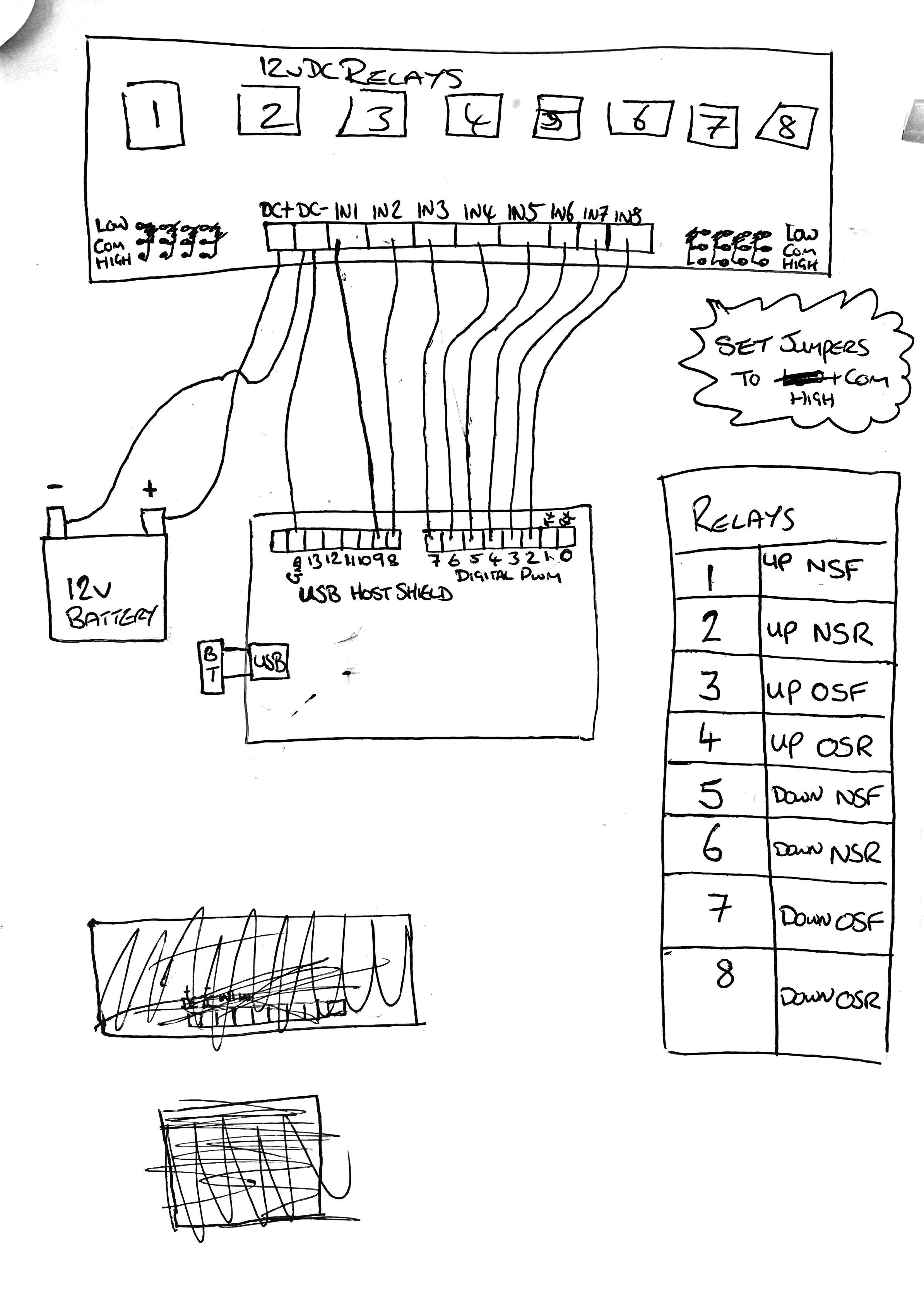
LOW jumpers mean low input to activate the relay.

From the comments in your code you are trying to activate the relays with a HIGH.
So if you are trying to get a HIGH to activate your relay, you need to move ALL the jumpers to bridge HIGH.
Currently the reason the other relays ALL come on is because you have the relays set LOW as activate.
Apart from output 2 relay cycling, ALL the other arduino outputs are currently LOW, so ALL the other relays activate ALL the time.
Tom... ![]()
TomGeorge:
Hi,
The spec/info for the relay assembly.
LOW jumpers mean low input to activate the relay.
From the comments in your code you are trying to activate the relays with a HIGH.
So if you are trying to get a HIGH to activate your relay, you need to move ALL the jumpers to bridge HIGH.Currently the reason the other relays ALL come on is because you have the relays set LOW as activate.
Apart from output 2 relay cycling, ALL the other arduino outputs are currently LOW, so ALL the other relays activate ALL the time.Tom...
Thank You Tom! This is exactly my issue ive just found out. I disconnected the jumpers from pins 3-9 and all but 1 went off (pin 2 was connected) so i changed the jumper from com-low to com-high and it works
my current relay is switching all relays in 5 second intervals so my code here works fine now i need to incorporate this into the ps3bt code on each button.
again MANY THANKS to all who have helped me.
here is my code for the relays
/*
  Blink

  Turns an LED on for one second, then off for one second, repeatedly.

  Most Arduinos have an on-board LED you can control. On the UNO, MEGA and ZERO
  it is attached to digital pin 13, on MKR1000 on pin 6. LED_BUILTIN is set to
  the correct LED pin independent of which board is used.
  If you want to know what pin the on-board LED is connected to on your Arduino
  model, check the Technical Specs of your board at:
  https://www.arduino.cc/en/Main/Products

  modified 8 May 2014
  by Scott Fitzgerald
  modified 2 Sep 2016
  by Arturo Guadalupi
  modified 8 Sep 2016
  by Colby Newman

  This example code is in the public domain.

  http://www.arduino.cc/en/Tutorial/Blink
*/

// the setup function runs once when you press reset or power the board
void setup() {
  // initialize digital pin 2-9 as an output.
  pinMode(2, OUTPUT);
  pinMode(3, OUTPUT);
  pinMode(4, OUTPUT);
  pinMode(5, OUTPUT);
  pinMode(6, OUTPUT);
  pinMode(7, OUTPUT);
  pinMode(8, OUTPUT);
  pinMode(9, OUTPUT);
  digitalWrite(2,LOW);
  digitalWrite(3,LOW);
  digitalWrite(4,LOW);
  digitalWrite(5,LOW);
  digitalWrite(6,LOW);
  digitalWrite(7,LOW);
  digitalWrite(8,LOW);
  digitalWrite(9,LOW);
}

// the loop function runs over and over again forever
void loop() {
  digitalWrite(2, HIGH);   // turn the Relay on (HIGH is the voltage level)
  digitalWrite(3, HIGH);   // turn the Relay on (HIGH is the voltage level)
  digitalWrite(4, HIGH);   // turn the Relay on (HIGH is the voltage level)
  digitalWrite(5, HIGH);   // turn the Relay on (HIGH is the voltage level)
  digitalWrite(6, HIGH);   // turn the Relay on (HIGH is the voltage level)
  digitalWrite(7, HIGH);   // turn the Relay on (HIGH is the voltage level)
  digitalWrite(8, HIGH);   // turn the Relay on (HIGH is the voltage level)
  digitalWrite(9, HIGH);   // turn the Relay on (HIGH is the voltage level)
  delay(5000);                       // wait for a second
  digitalWrite(2, LOW);   // turn the Relay off (LOW is the voltage level)
  digitalWrite(3, LOW);   // turn the Relay off (LOW is the voltage level)
  digitalWrite(4, LOW);   // turn the Relay off (LOW is the voltage level)
  digitalWrite(5, LOW);   // turn the Relay off (LOW is the voltage level)
  digitalWrite(6, LOW);   // turn the Relay off (LOW is the voltage level)
  digitalWrite(7, LOW);   // turn the Relay off (LOW is the voltage level)
  digitalWrite(8, LOW);   // turn the Relay off (LOW is the voltage level)
  digitalWrite(9, LOW);   // turn the Relay off (LOW is the voltage level)

  delay(5000);                       // wait for a second
}
Currently the reason the other relays ALL come on is because you have the relays set LOW as activate.
Doh! I missed that! ![]()
Keep in mind a schematic of the inputs ‘is needed’ to tell us how the inputs are powered.
example it might be:
12v - resistor - optoisolator - relay board terminal strip - Arduino output pin.
If the above is correct, you should use a ULN2803 between the Arduino and the relay board.
The reason for this is you would be mixing ‘relay 12v’ and the Arduino output pin which is 5v and ‘is not’ an open drain MOSFET.
If the jumpers allow the Arduino to turn on the optoisolator with a 5v output, the circuit might be as follows:
Arduino output pin - relay board terminal - resistor - optoisolator - GND
In this case no ULN2803 would be necessary.
If you have the skill set to trace to foil pathway on the relay PCB, you could easily tell us how the relay input circuitry is connected for each jumper option position, i.e. LOW/HIGH.
Barring any schematic information, I suggest you use the ULN2803 with this relay board, when set to the LOW option (just in case so your Arduino is not damaged).
Edit
In setup() you can make all outputs HIGH (for LOW jumper position) prior to making the pins outputs.
If you do use the 2803, remember it is basically a open collector ‘inverter’.


One last time, the possibility of your Arduino being damaged with this relay board exists when the Arduino is directly connected to it.
See my previous post.