Graynomad:
Load dump is something that should be considered, > 100V I think. Can the TVS etc handle that?
That is the question. It can handle 1.5kW for a short time (in ms). My goal is to shunt any short bursts to ground, and blow the fuse on longer anomalies. In all cases, I want the components to survive. At the very least, the PSU should sacrifice itself while protecting the load.
Since I have no desire to put my car through the wringer in the name of experimentation, I had considered testing failure modes by feeding the input from a 120v wall outlet for 100ms or so. (Maybe I should try 500ms to be safe.) I'm thinking this could be accomplished with a reasonably fast relay and, of course, an Arduino to sequence it. A 50ft extension cord and a concrete driveway being the test bench, of course.
spirilis:
The way I see it, if the accessory is on then you probably expect your gadget to be available.
This is the gist of my remaining concern with this feature. I can't think of any case where the difference between "accessory on" and "engine running" is of any real importance, but end users are funny like that. There is often an ignition switch as well, where the dash lights come on and the fuel pump engages and all that, but I don't think it will be accessible to most people without tearing into the steering column. I'm sure it's usually not going to be worth the trouble.
Look at this pdf it has a whole pic based system + input and driver circuits for 3-5ohm coils. I am also interested in an advance control but just starting to look into what it would take. I am going to start with hall pickup and coil drivers with the mechanical advance than move on from there.
Long time no post. Other projects demanding time and whatnot..
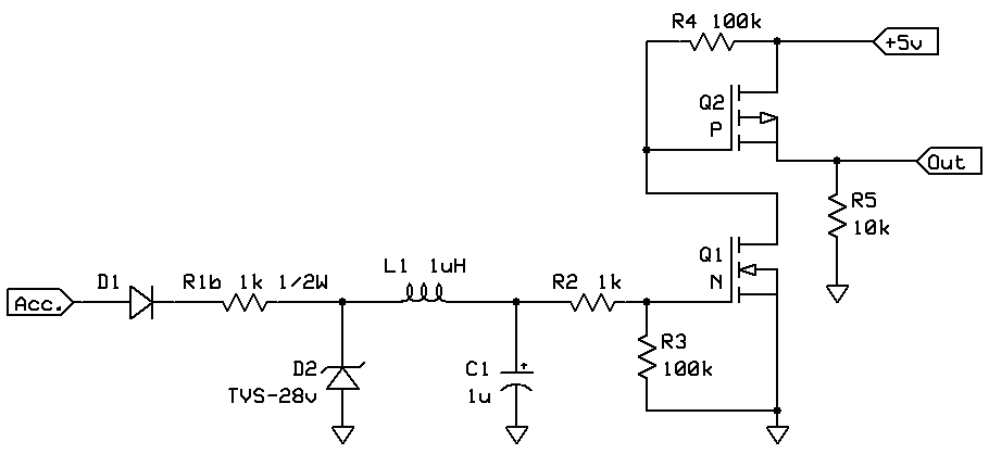
So, I'm putting together a test PCB design for this. I'd like to accommodate a switched "accessory" input, to provide a clean, protected 5v signal line to the downstream load.
My gut feeling is that the vehicle's accessory input should be protected to the same degree as the 12v power input. I.e., a diode, a TVS, and a current limiting resistor. Since the accessory input only needs to have enough current drive to turn on a MOSFET or something (remember, this just forms a TTL-level indicator), I should be able to use a higher value R1 (I dunno -- maybe even 1k?) and scale back the TVS and D1 diode to lower current parts, right? I'll do some simulations, just thinking out loud for now.
Looking back on car stereos and such, it seems the accessory lead is very rarely fused. But, I see no reason why I should treat it any different, w.r.t. its ability to start an electrical fire if shorted to ground.. Thoughts?
I was wondering how long it would take for someone to spot the 10 ohm resistor... Most devices of the nature you describe are ignition controlled so I wouldn't worry about 24 V jumps or reverse jumps to the car battery, sense when the ignition is on and let that control the input to your Power supply but no one really caught the real killer and that is Load Drop, a condition where the battery cables are loose or corroded and momentarily "drop" the Load from the alternator, alternators can and will produce a hundred or more volts when open circuited... It's hell on radios, lights, and most of the rest of the 'connected' electronics.
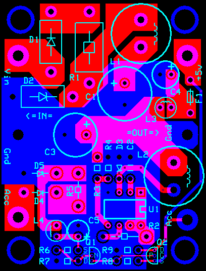
Preliminary reference PCB design. Any obvious design flaws sticking out to anyone? I still have to give it one final run-through comparing with the netlist and make sure I didn't make any mistakes, then print and populate to make sure the layout works.
BTW, this is designed for Express PCB's Miniboard service. Two will fit on a 3.8 x 2.5" board. With the minimum order, that gives me six to run through the paces and fine-tune. With any luck, maybe one or two of those will get to be production PSUs.
EDIT: Oops -- forgot to connect C1 to R2, which is the connection between the input filter and the regulator. Won't work very well without that! I can't see an easy way to resolve that, so it looks like I'll be doing some rearranging.
Finally got around to ordering the PCBs for this project. Here's one. I'm hoping to populate it and run some tests this weekend. If it works, I'll start torture-testing it to see how much abuse it can take before something breaks. >:-)
Graynomad:
Load dump is something that should be considered, > 100V I think. Can the TVS etc handle that?
Automotive transients can often be nearer to 400V than 100V - Intel produced a good application note AP125 on designing systems powered by automotive power lines. Here's a link http://ecee.colorado.edu/~mcclurel/iap125.pdf
You may want to study the datasheet hard: there were numerous errors in your design posted earlier.
Errors? Well, that doesn't sound at all like me. XD I should probably take the initial schematics down. I've fixed a few mistakes since then.
You may consider the beefier / simpler xx166/167.
I'm not familiar with that part. What's the xx? I know it's a placeholder, but what's an example that I can Google to find out more about it?
So, today's test was successful. I populated a board, wired it up to a car battery charger, stuck it outside where it could safely catch fire, crossed my fingers and hit the switch on the power strip. No smoke, no pops nor fizzles -- or were there...? It was outside afterall.
The green LED is the main +5v output. The red one is the Accessory output. Next up: Probing the output with an oscilloscope; testing with >24v input; and hooking it up to 120vAC. (That will probably be the final test for this board.)
I would like to use an Arduino in my 24V truck as well to monitor various sensors on the engine, and I'm very interested in your project. How did the testing go? I'm planning on using a GSM shield, which requires at least 1A to work well and probably need to run the whole unit with at least 7V.