My project I need to do involves keeping at tank topped up using a level sensor and a 12 volt solenoid on a pump outlet.
Distance between tank and pump is about 100 meters.
I was thinking about using cat 6 cable as the signal wire with either 5 or 12 volts from arduino board.
Is shielding required ?
Is this feasible considering the distance?
Can't use Wi Fi as there are concrete walls between pump and sensor.
I was going for a timed operation....sensor detects low water...solenoid opens for 10 minutes or I could fit another level switch at a higher level to switch solenoid off, what are your suggestions ?
Given its a DC sensor the main issue with a long cable run will be noise and interference pickup. Suggest putting a few nF of capacitance across the signal pair at the receiving end to help cut that down. A ferrite toroid for RF-suppression might be useful too (these are commonly present on USB leads to reduce emission, but here you want to reduce reception of RF voltages.
If the cable runs outside you might want to think about using an opto coupler to help with lightning protection?
Is the solenoid opening a valve or something? (I'm imagining a pressure actuated pump with a manual valve, and that makes me wonder about the possibility of putting a simple float valve in the tank...)
To have a simple float valve will require the feed line to be pressurised from the pump, the supply line will run across an open ceiling in a retail outlet....if the supply line ruptures at any point it will cause severe damage to property.... A - from the rupture acting like a fire sprinkler, B - the pump will continue to supply water to the ruptured line...could happen on a sunday night with no one around.
To reduce this risk the supply line will be non pressurised and opening into the tank....water flow will be when a solonoid opens from the pump outlet, there will be minimal pressure with the liquid transported this way, because the line isn't permanently pressurised then the supply line has less risk of failure.....if line ruptures then small amount of liquid will escape.....most will fill tank and shut the flow till the tank reduces in volume......this is more of a manageable risk.
xrayxray:
I was going for a timed operation....sensor detects low water...solenoid opens for 10 minutes or I could fit another level switch at a higher level to switch solenoid off, what are your suggestions ?
I would use both for safety. Low level sensor triggers pump on, time or high level sensor (whichever comes first) triggers pump off. Power on with solenoid deactivated and wait for low level sensor to trigger.
For sensor interface, I would use RS-485 serial with CAT-5 cable connected to a separate microcontroller on the sensor side. Use one pair for Rx/Tx and another pair for sensor-side supply (12V/Gnd).
For sensor interface, I would use RS-485 serial with CAT-5 cable connected to a separate microcontroller on the sensor side. Use one pair for Rx/Tx and another pair for sensor-side supply (12V/Gnd).
Are you suggesting an arduino and power supply with the float switch....and a separate arduino and power supply for the solonoid at the pump?
You dont think that the sensor switching can be detected at the required distance I want?
Are you suggesting an arduino and power supply with the float switch....and a separate arduino and power supply for the solonoid at the pump?
You could use a standard Arduino, but a simpler/smaller board such as Mini/Mini-Pro/(loads of others) might me more suitable. The sensor side controller board will need a voltage regulator taking its supply from the CAT-5 cable.
You dont think that the sensor switching can be detected at the required distance I want?
A digital sensor is generally much preferred even for moderate distances. RS-485 will work reliable for distances up to several kilometers. The use of differential signaling (RS-485) on twisted pair CAT-5 wiring is more or less immune to noise and electrically similar to the widely used CAN-BUS industry standard. Transceivers mate with hardware serial, they are easy to interface and available at low cost.
If it's a switch (on/off), it seems to me that distance would be somewhat irrelevant. Resistance and capacitance of the wires aren't a concern as they are for longer distances of data cable. The resistance on the input pin to the Arduino is significantly greater than the resistance of the wire, so using Ohm's law, we know most of the voltage is present at the input. Ethernet cable has a resistance of .188 ohms/meter, so the 200m in your cable has 37.6 ohms total, while the input has a resistance of 1M ohm. You should have VERY close to the source voltage at the input. Capacitance doesn't really do anything to a steady voltage, especially what little exists between the wires.
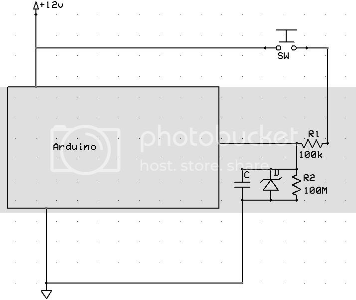
If you do have a problem with 5v for some reason, you could run 12v to the level switch, then have a resistor in series with the return wire and the Arduino. You would also need a 5v zener diode in parallel with a fairly high resistance resistor to ground between this resistor and ground. The series resistor would limit the current to something the wire and zener diode can handle, the zener diode would limit the input voltage to 5v after the series resistor, and the resistor in parallel with the diode would drop the signal voltage to zero when the switch opens.
This. The arduino has a voltage regulator that will take up to 20V and regulate it down to 5V, although it would get mighty hot if you used 20. The pins on the arduino are expecting no more than 5V
I can't see the point in using a second processor. I would use the float switch to ground one side of a 680 ohm resistor, other side of the resistor through an opto isolator to +12v. If it is a mechanical float switch then it may need a higher current to keep the contacts clean, in which case put a ballast resistor in parallel with the resistor/opto isolator arrangement.
Use the receiving side of the opto isolator to ground the Arduino input pin.
Design your circuit at the Arduino so the 'open' condition represents the 'no more water needed' state and I don't see any problem with that, unless the float or microswitch physically jam in the 'closed' position. How much of a problem would that be? Do you have an overflow in case the pump gets stuck on?
xrayxray:
a diagram would help me if you could point me towards one.
I was under the impression that my mega 2560 which im learning about was suitable for 12 volts...or does this only apply to the input voltage.
Regards.
I think you should be fine with using a 5v output from the Arduino, running that to the switch, and having a return directly to the input pin. You will want to use a pull-up or -down resistor to hold the voltage to a steady on or off so that noise picked up by the wire isn't seen as a the switch opening or closing. If the switch is normally open, then have a pull-down resistor so that when the switch is open, the input is held at 0 volts.
That is if 5v doesn't work for some reason, but I believe it should. The capacitor isn't necessary because you don't need to smooth an an/off signal, but I got used to putting them there on the projects I've done that used a variable DC input and didn't notice I'd put it there till after I looked at the preview.
The 12v is only the power supply. The actual inputs to the chip (and possibly the whole chip) will be damaged if you apply more than 5v to them. I accidentally put a pull down resistor to the power rail on my breadboard (12v) and it just took out one pin, but since you have one where you can't replace the chip, I would be very careful.
Step 1: feeding +12v to your float switch without even a series resistor means that sparks will fly if you get a short to ground at the float switch.
-Thanks for the advice.
Step 2: using a regulator to step 12v down to 5v is overkill. If you don't want to use an optocoupler as I suggested, use a voltage divider.
I am so new to this my head is exploding from taking it all in, wiki is helpful etc.....I understand your way is more economical....but for the moment i thought this might be a simpler(easier) solution for me, tho looking on the web I'm getting my head around some of it now....maybe hope for me yet,lol.
Step 3 - Good advice again - thanks.
There seems to be multiple ways of doing this project and everyone's input is fantastic,I have set up a bench mount mega to test and prototype before i get the parts and instal.
I have a switch mimicking a float switch, i have a breadboard and leds.
My aim is to have the leds run on after switch momentary on ( float switch )is activated and using the internal counter/timer for example 5 mins or more, mimicking solenoid open.
After i got this bit sorted I'll look at 2 level switches....low and high to keep the liquid between them.
I've been looking for sketches that do this...can't find any and looking for something i could modify....might be out of my league at the moment.
I am having trouble understanding all of this....not giving up tho...I'll keep googling till i find the solution....any help greatly appreciated.
This code stuff is hard to learn...am getting lost in it a bit...any guidance there?????once again i appreciate everyone's input.