For auto-reset to work correctly, it has to cause a reset pulse only during the transition of the signal from the 8u. that's because the host side software doesn't "toggle" the pin, it just changes the state as a result of "opening" the virtual serial port. If you're willing to make the host-side software specifically arduino-aware, you can just connect the 8u pin direction to the 328 reset pin, and use some other SW mechanism to create the reset pulse...
that's because the host side software doesn't "toggle" the pin, it just changes the state as a result of "opening" the virtual serial port.
I thought the arduino IDE (or is it AVRDUDE?) did perform an explicit DTR pulse right before performing the upload operation, rather then just relying only on the opening of the comm port by the OS?
Lefty
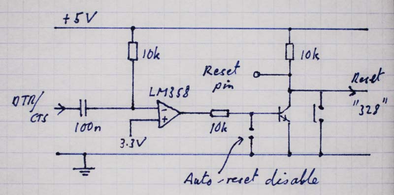
Ah, good point Westfw. Ok, here's another version. This one requires no modification of the 8U2 soft, and is also compatible with other commonly used serial interfaces.
It uses 3 extra components over the current version of the Uno: two 10k resistors and a transistor. The other components are already available at suitable positions on the board, including the op-amp. The reset pulsing remains exactly as on the Uno-R2, but the LM358 can withstand any over-voltage glitches applied to its input. The transistor allows external signals to be applied to the Reset pin without risk of damage.
-Tim
I thought the arduino IDE (or is it AVRDUDE?)
AVRDUDE is the culprit.
did perform an explicit DTR pulse
The Windows version pulses DTR and CTS for the "arduino" programmer type; the type used by Arduino 0022.
I'll investigate the *nix version tonight.
any more progress on this one? or is europe still on holiday?!
Nope,nope.
And due to lack of communication, the uncertainty it casts on the projects running on arduino, i've jumped off the boat.
I certainly don't want to be lost in the wild with a provider. Even if i had some discussions with the team.
Good luck everyone.
{EDIT}
To be specific, i choose other hardware not because the huge merits of arduino decreased. It is still a great platform, with lots of great things to offer. However, it was not the right choice for me, in my particular context.
I've had some discussions with the team, which helped me knowing their progress on the issue. We have some different vision about communication, that's all.
bump... once again, has there been any further progress? i still see postings all over the place from folks who can't program their UNO, etc boards, and nearly zero mention of adding a diode between RESET and 5V being offered. now i know that this diode will not fix every failure being reported, but i do strongly feel that adding a diode will help at least some people.
robert
can you send me a PM with links to all these posts that you are seeing?
There will be a post on the blog on friday about this
m
PM sent - i think! can you let me know if it made it to you ok?
cheers,
rob ![]()
Thanks Rob.
Certainly cured the problem for another board here as well.
AVRDUDE is not the culprit.
The issue is that the Arduino hardware needs a reset pulse and is (was) using DTR as
the stimulus for that reset pulse yet DTR is level/state driven signal.
DTR is not a generic i/o pin with respect to serial communications but rather has a well
defined behavior. Its normal behavior is that it is used to detect the presents of device.
So therefore it is not a pulse but a logic level signal that indicates that a device is
connected or it isn't.
Normally most operating systems try to provide the standard DTR behavior.
This means that DTR will be one level when the serial port is not open and another level when
the port is opened. Again, this is not a pulse but a logical level signal to indicate to the other end
that something is attached and "listening".
This even works if multiple processes/applications open the serial port. The state will
change when the first open occurs and revert back when the last close occurs.
Now while most operating systems provide the standard DTR behavior, most also
allow overriding this standard behavior. Some allow manual control of DTR and
some allow disabling the automatic DTR state changes when the port is opened/closed.
As far as having DTR directly controlled by things like AVRDUDE to create a pulse
vs a logical level signal, while it can be done,
this is not particularly a good idea as it requires depending on non standard behavior of DTR and
often requires modifying the standard operating system behavior to make this work.
Remember that since DTR is controlled by the operating system, the OS would have to be told
about the non standard behavior and permanently configured to use that behavior
on each serial port that connects to an Arduino, because by the time an application like AVRDUDE is up
and running the OS by default may have already changed the state of the DTR signal.
i.e. the OS has control of the DTR signal when the serial port is opened which is before
the application can modify the DTR signal level.
While many OS's like Windows and LInux can be told to use non standard DTR behavior,
the way it is done is different (even between different versions of windows)
and can require using command line tools (on linux) or registry edits (on widows) to
ensure that the changes are permanent.
I would simply not recommend going down that route particularly since there are other s/w based solutions.
RTS which is/was also used for auto reset also has a standard behavior. But in the case
of RTS, it is much easier to control manually from an application given the standard/normal behavior for
RTS signal levels will not change states when the serial port is opened/closed.
RTS by default is used for hardware flow control.
As long as hardware flow control will never be used or enabled, then RTS is a much
better choice as things like generating a pulse for a an arduino reset.
The only potential issue when using RTS is that if hardware flow control is enabled
and the AVR is slamming the port with data, the RTS signal might get asserted
which would end up reseting the Arduino board rather than expected behavior
of flow control.
Now why wasn't RTS used vs DTR from the beginning?
Good question, this is because to use RTS required software changes to the IDE
and/or AVRDUDE. Auto-reset could be "kludged" in using DTR with no changes
to the IDE or AVRDUDE. So people could solder a capacitor on their board
and enjoy the "magic".
Where it gets interesting is when using a standard FTDI USB to serial adapter
cable. These cables bring out the RTS signal but do not bring out the DTR line.
So in order to use them, you have to toggle RTS.
To accommodate using RTS the IDE was modified to toggle the RTS line on
the serial port before starting up AVRDUDE in case the auto-reset depended
on RTS vs DTR. (DTR would still be driven by the OS and not AVRDUDE).
In the mean time, AVRDUDE has now been extended to support
an arduino programmer type that knows how to toggle RTS (maybe DTR too?)
for auto reset.
Going forward, there are several solutions possible but in my mind you
shouldn't use hardware to solve a problem that can easily be solved in software.
So the current state of things is that the IDE toggles RTS before calling AVRDUDE.
This allows DTR or RTS to be sued for AutoReset.
Th latest AVRDUDE also has an arduino programmer type that knows how to toggle RTS
for AutoReset.
So given that RTS can now be used and avoids some of the DTR issues,
why use DTR for any new designs?
Also now that that there is a programmable part instead of a FTDI chip
you have complete control over the signal that controls the AVR reset line
and should not need to depend on the auto-reset cap "kludge" for the reset pulse.
My suggestion:
Simplify the hardware not make it more complicated.
This can be solved with Arduino board changes but mainly software changes to the 8U2 Code.
-
8U2 needs to either switch over to monitoring RTS instead of DTR or
it needs to be state driven off the DTR signal.
i.e. if DTR is still used, then pulse the auto reset output signal when DTR drops vs
mirror the DTR state. -
Hook the 8U2 signal directly to the reset pin of the AVR. (remove the .1uf cap or short it out)
So my suggestion is to modify the 8U2 code and then replace C5 with a zero ohm resistor
so that the board does not have to be re-spun.
It becomes a simple ECO to change the board stuffing from a capacitor to a zero ohm resistor.
--- bill
It might be difficult to add anything to the 8u2 firmware, since it currently fills all but 6 bytes of the available space.
I haven't looked at the code or the USB messages involved yet,
but if the DTR and RTS state come across in the same message, then
simply switching from using DTR to RTS might not use up any more code space.
If you switch from DTR to RTS then you can eliminate the capacitor since
the IDE and/or AVRDUDE can toggle RTS when an autoreset is needed.
(vs DTR which normally drops low and stays low while the port is opened)
UPDATE:
It looks like the same status message is used to communicate RTS state as DTR state.
So it appears that changing from using DTR to RTS will not consume any additional code space.
It is merely looking at a different bit in memory.
bool CurrentDTRState = (CDCInterfaceInfo->State.ControlLineStates.HostToDevice & CDC_CONTROL_LINE_OUT_DTR);
This single line would change to look at CDC_CONTROL_LINE_OUT_RTS instead.
So my recommendation for resolving this would be to change the 8U2 code to use
RTS state instead of DTR state, because it can be toggled by the host software.
In order to use this software fix, you have to eliminate the capacitor. The easiest
way to do that is to replace C5 with a zero ohm resistor.
These two changes when combined, will avoid having to respin the board.
(but maybe you do use a resistor rather than 0 to avoid potential shorts with the
reset button or other circuitry driving the reset line)
Now as an alternative, I'd actually modify the code to flip the direction of the port bit rather
than control the data bit itself since it really only needs to yank the line low for reset.
In other words, I would flip between driving the pin low and using the pin as an input
for a "high".
This way the output pin is not consuming any extra power by fighting the external pullup resistor
on the AVR reset line.
This change also would not consume any additional code space but would
actually save a few bytes of code as the init portion would no longer have to set the
AVR_RESET_LINE_PORT bit to 1 or set the AVR_RESET_LINE_DDR bit to be output.
The defaul values of 0 and input are what is needed.
Then when it is time to pull the reset pin low, all you have to do is set the port bit to be an output.
To set it high, make the port bit an input.
The external resistor on the AVR reset line will handle pulling the signal back up.
Not driving the pin high but flipping to input mode avoids any potential shorting issues
with the reset button as well.
--- bill
the biggest problem is backwards compatibility - the IDE still needs to be able to communicate with EVERY existing arduino board out there, containing various bootloaders, firmware, and hardware configurations.
the whole auto-reset is an admirable intention that has, over time, and with various 'tweaks' become an absolute nightmare. the problem has been compounded by attempts to stick to a single codebase across several OS platforms, each OS with it's own level of access to and support for the usb and/or serial hardware.
personally, i'd do away with the auto-reset completely. instead i'd use a far more robust manual reset system:
- IDE pops up a window saying "PRESS and HOLD reset button..." with a counter going from 5 seconds down to 0
- IDE then closes that window and pops up another window saying "RELEASE reset button NOW".
during the above two steps the IDE would send repeatedly a query command to the bootloader, monitoring for a bootloader response. when the correct response came back the IDE would know that a communications channel with the bootloader had been established. if no response is seen within 5 seconds of the second window being popped up, a 3rd window could be popped up saying "Unable to Communicate". all very simple.
if someone is bright enough to program an arduino, they should be bright enough to press and release a single button as instructed!
Exactly.
That is why any prosed fix to UNO should be 100% backward compatible with the currently shipping
0022 and 1.0RC host software.
The proposal I suggested, required no changes to any host software.
It is changes that are isolated to the UNO board hardwre and 8U2 software.
It makes the UNO work like boards that use the official FTDI data cable by changing its auto-reset
to use RTS vs DTR.
(official FTDI data cables, don't bring the DTR signal out on the connector, they use RTS instead)
And while the proposal I made may not be the final solution,
I still believe that there is a solution for UNO that would not require re-spinning the board.
I think the key is what to insert in place of the c5 capacitor that is currently in series with the
auto-reset signal.
A diode? A resistor? Some sort of resistor probably makes the most sense since
it will prevent shorts to the RTS line from people either grounding or setting RESET to VCC.
the whole auto-reset is an admirable intention that has, over time, and with various 'tweaks' become an absolute nightmare. the problem has been compounded by attempts to stick to a single codebase across several OS platforms, each OS with it's own level of access to and support for the usb and/or serial hardware.
personally, i'd do away with the auto-reset completely. instead i'd use a far more robust manual reset system:
- IDE pops up a window saying "PRESS and HOLD reset button..." with a counter going from 5 seconds down to 0
- IDE then closes that window and pops up another window saying "RELEASE reset button NOW".
during the above two steps the IDE would send repeatedly a query command to the bootloader, monitoring for a bootloader response. when the correct response came back the IDE would know that a communications channel with the bootloader had been established. if no response is seen within 5 seconds of the second window being popped up, a 3rd window could be popped up saying "Unable to Communicate". all very simple.
if someone is bright enough to program an arduino, they should be bright enough to press and release a single button as instructed!
It sounds like you are assuming a particular method of uploading (a serial based bootloader).
and that the IDE has full control over the bootloader protocol.
If so, both of those assumptions are either incorrect or too limiting.
The IDE allows using many methods of uploading including ISP and proprietary methods like Teensy.
These alternate methods have no issues with auto-reset.
Even in the case of using a serial based bootloader, the IDE does not control the serial data
transfer. That is all handled by AVRDUDE.
So now you are talking about a much bigger change that involves not only coming up with a new
handshake and upload protocol but also potentially either moving all the upload functionality into the IDE
or adding additional functionality to AVRDUDE.
Also, take a close look where the reset button is located particularly on the official
arduino boards. How are you going to press that button when a shield in in place?
I believe that downloading from the IDE should "just work" rather than require people to hold
their mouth just right and have to push buttons on the Arduino board at just the right time
to initiate the download.
So, at this point, I believe it will be much easier to simply correct auto-reset issues that exist
once and for all in the Arduino hardware and software rather than dream up entirely new download mechanisms.
While auto-reset may have issues, IMHO, most are self inflicted by a lack of understanding of how DTR and RTS really work
and a lack of coordinating the host software to properly use the control lines.
I also believe that the majority of people are not experiencing auto-reset issues.
Yes there are many auto-reset issues with trying to use the Arduino as and ISP
but most users are not doing that and most of those issues can be traced back
not providing adequate auto-reset control on the board.
i.e. using DTR and not providing something as simple as a jumper to disable auto-reset.
There seems to be a bias to keep trying to solve the problem by throwing hardware at a problem
that needs to be solved by taking a different approach which probably involves software.
The key to having a reliable auto-reset is to have full control over the Arduino's reset line
by the host software.
While DTR can be used to control auto-reset, it is ugly and problematic because DTR is a level based signal and
the host application often does not have full control over the DTR line.
i.e. the OS usually controls and alters the DTR line state before the host application could ever take control.
IMHO, using RTS is the long term answer as it can be better controlled than DTR.
Since it can be toggled by the host software when needed/as needed,
there is no need to have hardware on the Arduino board attempt to make a pulse from a falling edge
level based signal.
The problem then reduces to how to keep the auto-reset signal from colliding with other
signal sources that drive the RESET line locally on the board.
All the Aduino IDE OS's currently supported allow controlling RTS from the host software.
The existing IDE and AVRDUDE both now have the ability to control the RTS line
and do toggle RTS for those Arduino board implementations that use RTS instead of DTR.
The current IDE toggles RTS which allows boards that use DTR or RTS to function even
when using older AVRDUDE that does not have the arduino programmer type that knows
how to toggle RTS.
So backward and forward compatibility is pretty well covered right now.
To me the ideal solution for auto-reset is to use RTS instead of DTR since applications
have much better control over RTS.
In addition, to accommodate those with very special needs for disabling autoreset, provide a jumper.
For a board like an official Arduino board like an UNO, if it were up to me, I'd put
a set of holes for a 2 pin header that has a trace between them. That way if a person
really wants to disable auto-reset for good, they can cut the trace.
If they want to use a jumper, they cut the trace and solder in a 2 pin header.
That way the less technical folks get a nice easy to use auto-reset from the IDE with no jumpers
and those with special needs can perform a simple "hack" to get what they need.
With a solution like that, you continue to get auto-reset for normal sketch downloading
and those that want to use the arduino as an isp can simply cut a trace, install a header/jumper
and disable auto-reset whenever they want/need to.
Also, when using RTS instead of DTR, you won't get the Arduino board reseting
when you open the serial port. You only get a reset during a download.
--- bill
Irrespective of the rest of this,
bperrybap:
For a board like an official Arduino board like an UNO, if it were up to me, I'd put
a set of holes for a 2 pin header that has a trace between them. That way if a person
really wants to disable auto-reset for good, they can cut the trace.
If they want to use a jumper, they cut the trace and solder in a 2 pin header.
Yes. That would be nice.
Was this posted to the Arduino Blog, or elsewhere? Didn't find any mention on the Arduino Blog, and looking forward to seeing this through.
One simple solution to this issue for all Arduinos out in the field is a simple 2 pin jumper with a 5V6 Zener diode fitted (BZX55B5V6-TR ~ 3 cents), along with clear polarity markings for fitting across pins 5 & 6 of the ISP header. Such a solution could be posted 1st class folded in thin cardboard inside a standard envelope for next to nothing for those who want it. Of course it would need to be tested, I don't have such a zener diode handy.
In terms of implementation one would need to mount the zener on the side of the open jumper because:
- It needs to be low profile (not interfere with shields etc..)
- It then acts as a physical polariser, the zener physically prevents it being fitted around the incorrect way as it hits pins 3 and 4.
regards
Al
im not sure if this issue has been discussed in a more recent threads. google directed me here. links to any other discussions, if any, would be appreciated.
first arduino team deserves commending for developing such an excellent software platform and showing great care in publishing fixes for these kind of problems. as an ee having designed and produced thousands of arduino and other avr devices (commercial and hobby) many similar cases of boot failure have cropped up. imo direct connect of reset is a bad idea for reasons mentioned. ive seen that cap save butt in more than one setup. the diode fix is the way to go. an even simpler remedy is just replace the 10k with a diode. i suspect that resistor serves little purpose anyway and has caused failure itself in some cases. swapping resistor with diode requires no changes to avrdude, gui, 8u, or arduino pcbs and has solved the problem of that hv spike for me. if there are unseen drawbacks in this approach please comment as im preparing to turn out another batch of units.
btw i understand arduino company has upgraded new board design but is there a more public link/sticky for the thousands of legacy users who run into this? i have some people who need more direct and non-technical info than this thread.
john1993:
i have some people who need more direct and non-technical info than this thread.
This is a technical problem, and I don't know that there's any way to state it more simply and directly than in this post:
and Google Code Archive - Long-term storage for Google Code Project Hosting.
Applies to Uno through R2, and Duemilanove, AFAIK.
So, patch your Arduino, if applicable, as shown in the circuit drawing.