raschemmel:
How big is a 20 H inductor (10A) ?
10 H about a house brick size at 50 Hz
20 H was at a uni for something special and about the size of a bus.
Edit
And its voltage rating was a tad above normal too.
raschemmel:
How big is a 20 H inductor (10A) ?
10 H about a house brick size at 50 Hz
20 H was at a uni for something special and about the size of a bus.
Edit
And its voltage rating was a tad above normal too.
10 H about a house brick size at 50 Hz
What dimensions are you talking about ? (L,W, H )
20 H was at a uni for something special and about the size of a bus.
Oh, yeah, you should be able to get a relay to switch that at RadioShack.... ;D
MarkT:
so MOSFET wins for that by fast switching time.
Dos this look like a practical switching proposition
Oh well, without a proper and detailed explanation of the real problem, I'm out! ![]()
10 H inductor size
http://uk.mouser.com/ProductDetail/Hammond/193M/?qs=5ZsRU9L2PDkh6DwnkLqAbg%3D%3D
That's only 0.3A though.
0 to 20 H was a bit of a wide guestimate.
Its likely in any case ill have to roll my own.
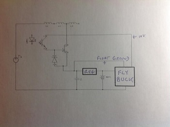
No its a flybuck convertor, a particular implementation of the flyback arrangement.
A relatively new term coined I suspect by TI.
Its advantage is that it has a floating ground.
Real problem.
I need a variable inductor I can control digitally,
I don't want mechanical.
Its for psu smoothing where capacitive does not work.
Here they refer to a dc bridge.
http://www.ijcee.org/papers/278-E747.pdf
Following the references finds other papers with somewhat circular reference with none adequately
describing its implementation.
I experimented years ago with similar and had little joy.
Its rather lossy at anything but a fixed frequency.
For wind power that's a bit problematical.
Rough experimentation with a kludgy homebrew variable inductance made me believe that this was the solution.
I am truing to devise an experimental rig controlled by an arduino to test further.
If anyone has better ideas I would like to hear them.
The actual implementation will likely have 10 or so taps, initially and I wish to keep cost down.
I would like to be able to compare as many motors as possible over a range of 50W to perhaps 2 KW and I am not sure yet what the inductance is likely to be required.
It looks like I have made a bit of an error in my sums.
Inductance range should be 0 to 2 H.
In principle its identical to avr used for generators in the 50 s.
Just a different implementation.
Boardburner2:
Dos this look like a practical switching proposition
No, it will explode - did you read my previous post?
Ok so I have to take off line before switching.
That's not a problem for test purposes I figure a couple of cycles with zero crossing switching.
Is this feasible.
A motor driven inductor may be a better solution but these days I have no idea where I would find one.
Edit I have seen the results of switch gear arcing.
I m testing at low voltage deliberately and power components are going in a 1/8 steel box.
No, it will explode - did you read my previous post?
I think the damage will extend to everything but the inductor. I don't think it would be damaged.
You might cause insulation breakdown in the inductor too...
You know how old car ignitions worked? Basically like this but with a much
smaller coil.
OK, looked at your reference.
Nowhere does it make any suggestion whatsoever for a need to vary, or benefit to varying, the inductance.
There is no theoretical reason for doing so.
The purpose of the inductor is a low-pass filter to maintain a relatively constant current from the rectifiers which is going to be more efficient in the coils of the generator and presumably improve the excitation current, but it is not in a resonant circuit (in fact, resonance would be extremely undesirable) of any sort so there is no requirement for "tuning".
Therefore the maximum inductance will be essentially equally effective for any generator frequency.
C. Diode Bridge Rectifier and DC Link
Three phase diode bridge rectifier is used to convert
variable magnitude, variable frequency voltage at the
induction generator terminal into DC voltage [3].
Input transformer’s turns ratio is 1:ηi The series reactor
(L) and shunt reactor (C) acts as an input filter. The current
ripples and voltage ripples are reduced by using the above
components [5].
Dc Link current is governed by the following equation
(1/ )( ) dc dc r i dc dc pi = L V −V − r i (10)
Where, RDC and LDC are the reactor resistance and
inductance respectively.
D. PWM Inverter
The output power of the rectifier is filtered by using the
LC filter. By using PWM inverter DC power is converted
into AC power employing double edge sinusoidal pulse
width modulation technique [5]. The PWM signals are used
to switch on the IGBT’s in the inverter. The IGBT’s are
connected anti parallel with the diodes. If diode conducts,
energy is fed back to the source. A carrier wave is compared
with the reference signal corresponding to a phase to
generate gating signals. The instantaneous line – to – line
output voltage is Vab = VS (g1-g3).
"shunt reactor " ? (where is that ?)
Paul__B:
OK, looked at your reference.Nowhere does it make any suggestion whatsoever for a need to vary, or benefit to varying, the inductance.
There is no theoretical reason for doing so.
The purpose of the inductor is a low-pass filter to maintain a relatively constant current from the rectifiers which is going to be more efficient in the coils of the generator and presumably improve the excitation current, but it is not in a resonant circuit (in fact, resonance would be extremely undesirable) of any sort so there is no requirement for "tuning".
Therefore the maximum inductance will be essentially equally effective for any generator frequency.
Sorry to disagree but.
Varying the inductance was a classical way of controlling the output voltage back in the day.
When I first experimented with this gear modern switchmode convertors were not commonly used.
Its not just frequency but voltage at work.
With variable speed from wind you get variable voltage as well.
Nowhere does it make any suggestion whatsoever for a need to vary, or benefit to varying, the inductance.
No it does not but my previous experience suggests otherwise and I never found a means to explain it at the time.
But it fails to describe the implementation of the dc bridge and size of motor yet elsewhere says that it does not work well for small motors.
I have time on my hands and thought I would try to devise an experiment to verify.
The output power of a wind generator is a function of the work (wind power) put into it, not the variation
of an LC filter. The output of the motor is AC which then rectified and the output stage is essential an inverter that functions like any other inverter, having a DC input voltage and IGBTs which turn on or off to
provide the positive and negative phases of the output AC voltage. I have to side with Paul that there is no basis for varying the inductance of a filter. I think you are just fiddling with the design without adequate background in power electronics design.
raschemmel:
. I think you are just fiddling with the design without adequate background in power electronics design.
You are quite correct.
Earlier experiments i did however did not agree with accepted theory.
Smaller motors do not seem to obey the same 'laws'.
No one seems to have addressed this adequately and I think the published papers have 'holes' in them as well
raschemmel:
"shunt reactor " ? (where is that ?)
❝Input transformer's turns ratio is 1:ηi
I take that to mean an unspecified capacitor but not sure.
What input transformer ?
All I can see is a coil
Its not a huge problem just something I would like to satisfy my curiosity on.
I am trying to devise a not to expensive experimental setup to satisfy that.
The practical solution is to use a permanent magnet generator for small systems but in the uk its probably much better to go for solar rather than wind.
raschemmel:
The output of the motor is AC which then rectified
Yes but with with IMAG the normal capacitive filtering does not work and inductive seems to fail also under some circumstances (which I do not know).
Do you actually have the Inductor to do this?
Transformers cant be used as Inductors if DC is going thru them , as without an air gap in the core, which inductors used in lo pass filters have , the transformer will simply saturate.
raschemmel:
"shunt reactor " ? (where is that ?)
I think it is a relative.

mauried:
Do you actually have the Inductor to do this?
Transformers cant be used as Inductors if DC is going thru them , as without an air gap in the core, which inductors used in lo pass filters have , the transformer will simply saturate.
No as per first post.
Been looking for an old variable one for years but they just do not seem to come up these days.
Late 60s I inherited some of an ex amateurs shack which had one.
But I discarded it as I could not pick it up....