after doing more research and with the help of others I have gathered from the data sheet how the fan is to be controlled on the PWM input pin. The circuit structure to drive the pin PWM / E can be any active low “open collector” Typical circuitry In this operating mode the supply voltage plus is usually connected permanently. To run the Drive on the pin PWM* / E* a PWM signal has to be applied and with the duty cycle of the PWM signal the Drive speed can be then controlled **
I have also connected the fans positive and negative to the battery supply voltage(12.5V) and got the same voltage out of the fans PWM*/E* pin. From the help of others on the Arduino forum I have been informed this is confirmation that the fan is controlled by an open collector circuit.
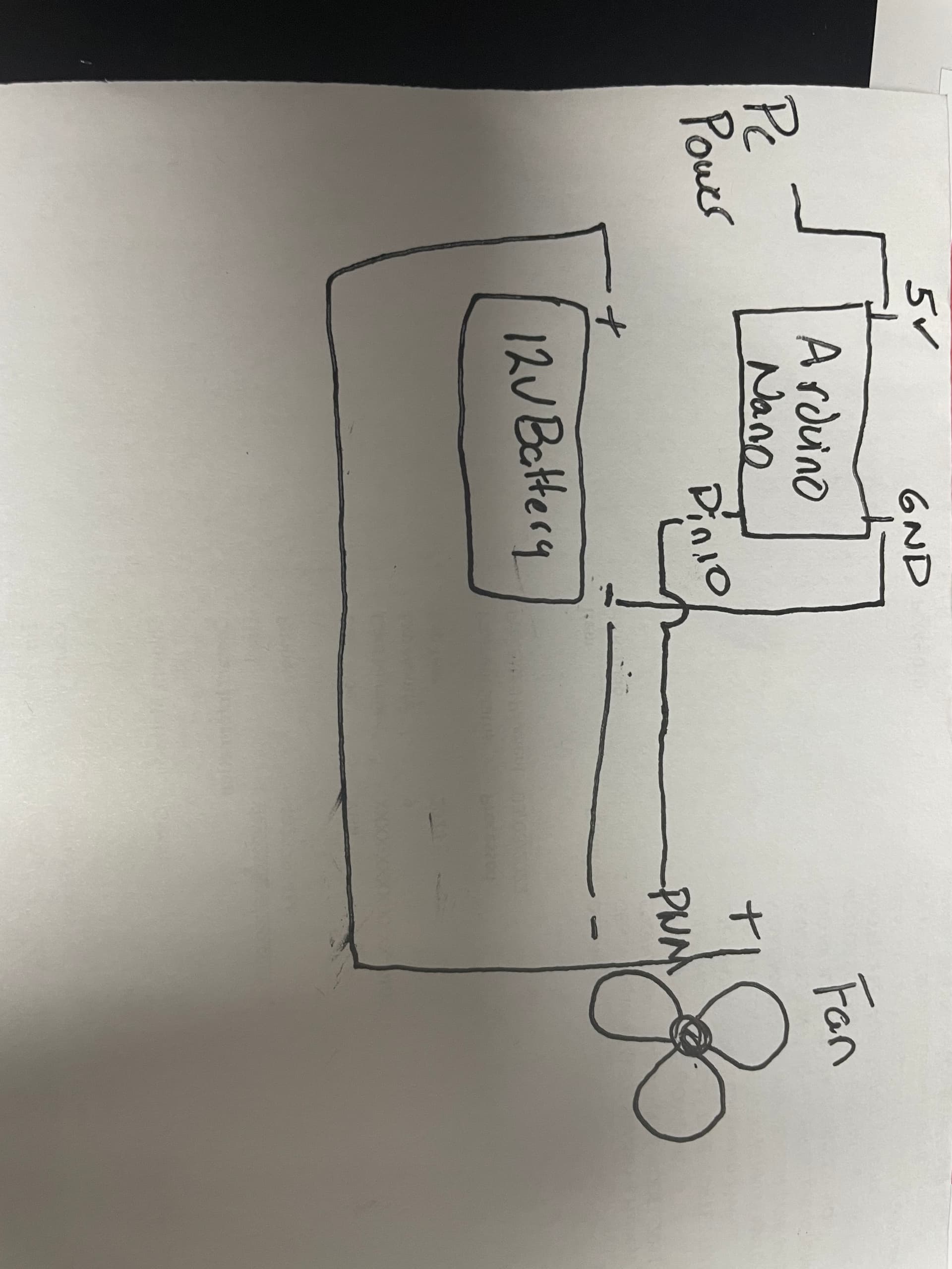
I am currently trying to generate a 128hz PWM 5V signal to command a brushless cooling fan for a car, I will upload my very basic code, the library used, and a schematic from desktop. Currently I am not able to command the fan to turn on and am just curious mainly if maybe what I am trying to do is not possible or if I am just making an error somewhere
using arduino nano
Writing the PWM value over and over and over and over is probably not how the library expects you to control the pin.. Did you look at the library examples?
/*

 Mimics the fade example but with an extra parameter for frequency. It should dim but with a flicker
 because the frequency has been set low enough for the human eye to detect. This flicker is easiest to see when
 the LED is moving with respect to the eye and when it is between about 20% - 60% brighness. The library
 allows for a frequency range from 1Hz - 2MHz on 16 bit timers and 31Hz - 2 MHz on 8 bit timers. When
 SetPinFrequency()/SetPinFrequencySafe() is called, a bool is returned which can be tested to verify the
 frequency was actually changed.

 This example runs on mega and uno.
 */

#include <PWM.h>

//use pin 11 on the Mega instead, otherwise there is a frequency cap at 31 Hz
int led = 9;                // the pin that the LED is attached to
int brightness = 0;         // how bright the LED is
int fadeAmount = 5;         // how many points to fade the LED by
int32_t frequency = 35; //frequency (in Hz)

void setup()
{
  //initialize all timers except for 0, to save time keeping functions
  InitTimersSafe();

  //sets the frequency for the specified pin
  bool success = SetPinFrequencySafe(led, frequency);

  //if the pin frequency was set successfully, turn pin 13 on
  if(success) {
    pinMode(13, OUTPUT);
    digitalWrite(13, HIGH);
  }
}

void loop()
{
  //use this functions instead of analogWrite on 'initialized' pins
  pwmWrite(led, brightness);

  brightness = brightness + fadeAmount;

  if (brightness == 0 || brightness == 255) {
    fadeAmount = -fadeAmount ;
  }

  delay(30);
}
would really like to create a simple code that outputs 128Hz at a specified duty cycle constantly
That's not what your code does. Your code does a 500 or 1000Hz (depending on the pin used) 50% duty cycle signal, if and ONLY if you're using a pin that has pwm capability.
You're confusing duty cycle and frequency. They're different things.
Also don't assume your fan reliably spins up at any given frequency and duty cycle. It won't. You'll have to experimentally determine for each given pwm frequency what the reliable spin up rate is and how low you can dial the dury cycle back (once it's alresdy spinning) for it to keep turning. The latter will be a much lower number than the former.
You CAN modify the pwm frequency on an arduino and just about any microcontroller.
So I was misunderstanding the function of this library, I thought I was able to modify the frequency and duty cycle. do you happen to know of any easy to use libraries that will accomplish my goals ?
Never looked into it to be honest, but I would suspect so. I would just manipulate the clock divider register for the timer used; it's just one line of code, but takes some studying to understand what you're doing. I'm sure someone has already written something to make this more user friendly.
yes unfortunately SPAl does not have a great data sheet, I will reach out now to their support line to see if I can find out if its expecting 12v or 5v for the pwm signal.
it was my understanding that the fan was looking for 5V 128Hz pwm 5-95% duty on that PWM*/E* pin, I just reached out to SPAL to verify what voltage and frequency the controller is expecting.
from what source? The data sheet contradicts that. It says nothing about frequency, though... there is no voltage spec, because it's an open collector drive.
this fan is a direct replacement for a General Motor fan and is supposed to be plug and play with the pwm signal from the engine controller, I looked at the data sheet for 2016 corvette cooling fan control and 5V 128Hz pwm 5-95% duty is what I found.
so after reading the SPAL data sheet again I see where it says any open collector, when driven low it will command the fan to full speed. I am trying to use the Arduino in place of the corvette engine control module PWM signal. I am working now to get an oscilloscope to read the signal the Arduino is generating. I also reached out to SPAL for more information about frequency voltage and duty cycle range.
Why, when that is fully documented and understood? I think, unless you phrase your question about voltage to the support staff very carefully, you won't get a definitive answer. It's easier to go measure it. Look at the voltage on the PWM in pin with power applied to the fan.