Hey, I want to drive a 12V DC 2-wire 0.47A blower fan. As it only has 2 wires, I thought of controlling the fan speed via the voltage I provide it. I want to control the voltage through a PWM signal from an Arduino uno.
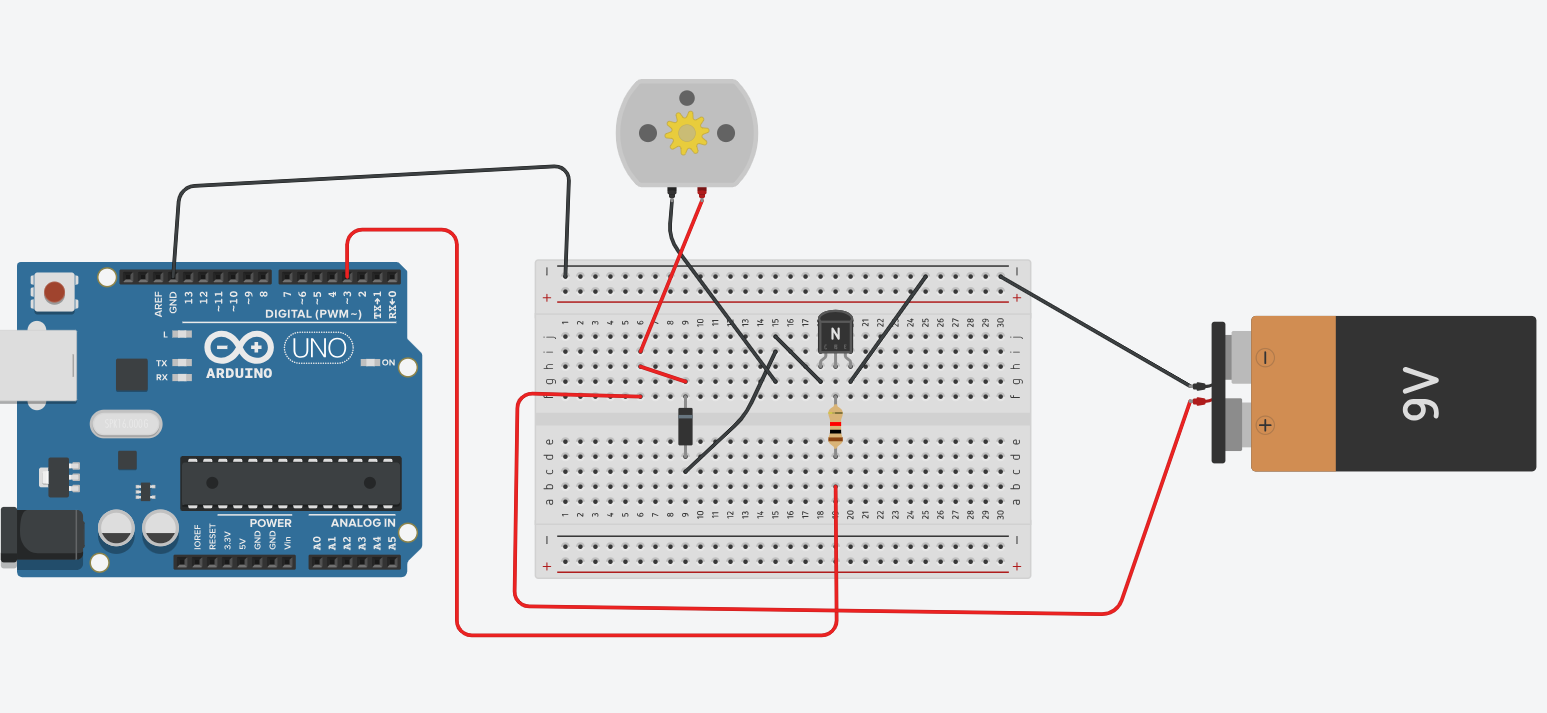
I have created the following circuit in tinkercad, just to see if my circuit makes sense or not. The battery in my schematic is 9V (instead of a 12V battery) and I put a motor as a placeholder (instead of a 12V 2-wire fan).
First of all, is my circuit correct in general?
Secondly, how do I go about choosing the appropriate components for the circuit?
What would be an appropriate resistor value in front of the base of the transistor?
What transistor should I use?
What zener diode should I use as a flyback diode? (or is there a better alternative?)
Thanks in advance! If anything is unclear, please ask questions!
If that's a brushless motor, it may not work well with PWM.
A BJT (bipolar junction transistor) probably can't carry the 470mA current, an N-channel, logic level MOSFET would be better.
Post a link to the fan's datasheet or the seller's webpage.
I actually sent PWM to 48 volt fans. It's important to use a low PWM frequency. The supplier of the fan said it couldn't be speed controlled. It sure did!
Think like this: If You make short time connection to the fan, it starts and make a few revs. Repeat the short time powering at a suitable rate.
Maybe it would be fare to talk about pulse frequency modulation instead of pulse width modulation.
Logic Level N-Channel Mosfet such as an IRLZ44
22 Ohm resistor for RG
1N5419 diode flyback
slightly adapted circuit, as i learned that an extra resistor might help avoid accidentally switching on the transistor for example when the arduino starts