Thank You for You suggestions and update on the sketch.
The batteries can discharge in -20 / +55 deg. If the rover operate on the field, then the temperature can make a significant impact on battery capacity.
Just to make the study complete:
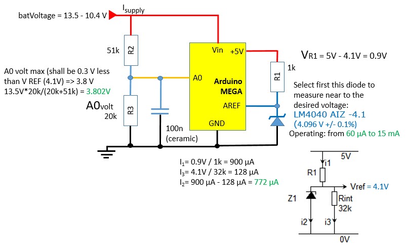
For external reference voltage version, I followed this link and made a schematic for 12V version.
Is used for Analog Pin A1. So analogReference(INTERNAL2V56); obsoleted.
The data sheet for LM 4040 is attached. The script can be figured out.
Now I turned my attention to septillion's easy calibration proposal.
Let say initially I have 12.1V on battery (measured with DMM).
After voltage divider: UA0 = 12.1V * 10k * (10k + 47k) = 2.122V
If I run separately analogRead(BatVoltPin) this will give somewhere adcValue = 434.
If during the operation, I get let say adcValue' = 378, due to linearity:
12.1V/434 = Vcc/378 -> Vcc = 12.1V * 378 / 434 = 10.538 V (actual battery voltage during operation)
The updated sketch for Your kind consideration and review:
const unsigned long BatVIni = 12100;   //mV  measure only one time, when connected to the circuit
const unsigned long AdcValueIni = 434;	//  to get, run once separately analogRead(BatVoltPin),
                                       // in the same time when BatVini measured. Only one time required.
const unsigned long BatRatio = BatVIni / AdcValueIni;
const unsigned long BatVoltMax = 13500; //mV
const unsigned long BatVoltMin = 10400; //mV
const byte BatVoltPin = A0;     //Analog pin # A0
const unsigned int NrSamples = 1000;   // Usually from 5 to 10000

byte batteryPercentage() {
  unsigned int adcValue = averageRead(BatVoltPin);  // let say it is 378

  unsigned int batVoltage = adcValue * BatRatio;  //mV; let say it is 10538 mV

  Serial.print("Batery voltage [mV]: ");
  Serial.println(batVoltage);
  byte percentage = 100 * (batVoltage - batVolt_Min) / (batVolt_Max - batVolt_Min);  // to be improved
  Serial.print("Battery level [%]: ");  //<= statement ends, next line please!
  Serial.println(percentage);

  return percentage;
}

unsigned int averageRead(byte pin){
  unsigned long total = 0;
  for(unsigned int i = 0; i < NrSamples; i++)
  {
    total += analogRead(pin);
  }
  total += nSamples / 2;   // add half a bit
  return (total / NrSamples);
}
I just one note to the external Vref with LM4040.
Is it possible, that the diode is not so accurate ?
According this (John Errington's Experiments with an Arduino): link link for sample code
In the script mentioned the following:
// for voltage conversion
float vRef = 3.390; // the accurate value of your reference eg 4.096
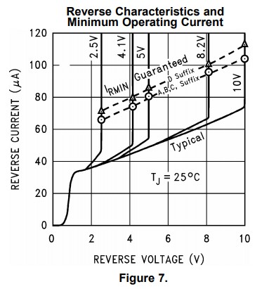
As per data sheet, the typical is: 4.096 V
Can be the difference: 3.390 / 4.096 = 0.82 -> 18% ?
In this case (despite the diode) the voltage on the diode must be measured and hard-coded in the script!
Which grade do you use? But I don't believe it will ever be that low (if biased correctly). It would also be wiser to bias it from 5V to keep the bias current more stable.
But why not use it as the voltage reference instead of measuring it?
For LM4040 the following ranges can be used:
2.048 V +/- 0.1%
2.5 V +/- 0.1%
3.0 V +/- 0.1%
4.096 V +/- 0.1%
I preferred 2.048 V version, because it give better resolution after ADC.
@steger There are way more versions (grades) than that. Both in static accuracy and temperature coefficient. And yeah, it doesn't matter which version you use, as long as you know what you use and reflect that in the software. But after a quick scan of the datasheet, 3.390V instead of 4.096V seems outside any spec you may expect from it.
And again, why not use it as the actual reference instead of measuring it and compensate the other reading?
septillion: I got Your point. The voltage remain the same, no single change, just feed with min. 60 uA as the datasheet showing. I thought it is slightly changing, that is why the author of the script put the corrected value 3.390 V instead of 4.096 V.
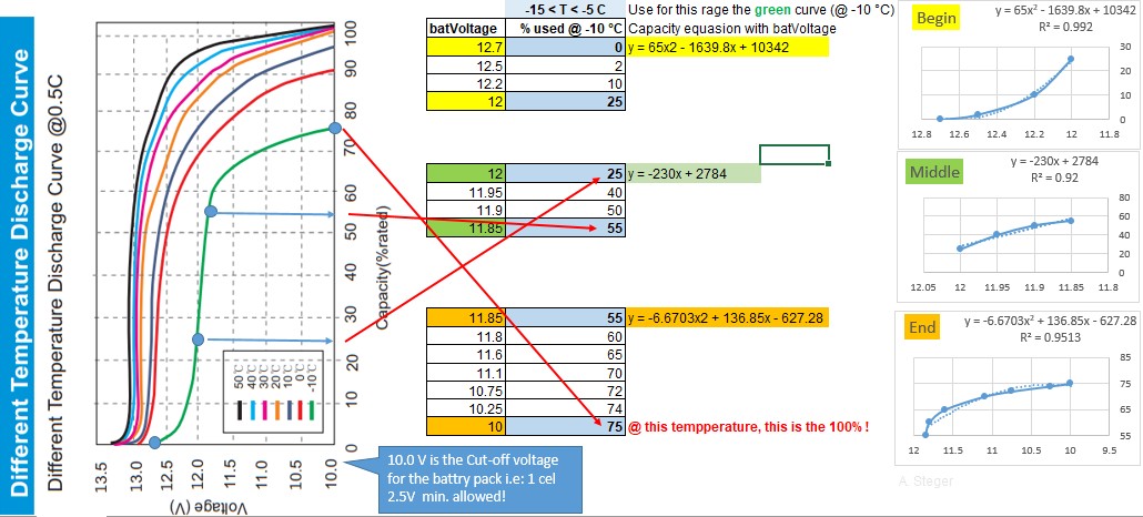
After so many improvements, I would like to involve the temperature in the battery capacity (percentage) calculation.
For case study with LiFePO4 battery, I selected this source: link and the attached picture (discharge).
-> If Your have better source, like with numbers/ (%&Volt) data, which generating the graph itself, then kindly share with us, because those data can be used for non-linear regression. (Instead of manually figure out the points from the below graph.)
And again, why not use it as the actual reference instead of measuring it and compensate the other reading?
Many "arduinos" dont provide a connection for an external reference, so if you were using one of those you could use the calibration source approach as in my sketch.
However in that sketch
// for voltage conversion
float vRef = 3.390; // the accurate value of your reference eg 4.096
/* *** change the value to match the reference voltage you are using *** */
means put in the value of your chosen reference.
So if you are using a 2.3653V reference thats what you put in.
Your misunderstanding has been very useful feedback, and I've amended my page.
@ johnerrington: Thank You very much for Your guidance.
So my external reference shall be as high as possible, because I already would like to measure more than 5V.
I selected your proposal LM4040 AIZ -4.1V
The voltage on the divider shall be approx 0.3V less. (because the 4.1V will be the '100%')
So it will come: 3.8V. I changed the resistors accordingly. (20k & 51k receptively.)
The diode will get the supply form +5V out from MAEGA. (Not from 12V.)
For this, I have to select R1 protection resistor accordingly, so min.60 μA, max. 15 mA can flow through the diode.
I attached the modified schematics. I hope it is fine.
If I write:
analogReference(EXTERNAL);
value = readInput(A0);  //it will correspond to 4.1 V accurate; i.e: 4.1V == 1024 (and not to 5V, not so much accurate)
adcValue = averageRead(A0);
voltageOnPinA0 = 4.1 * adcValue / 1024;
batVoltage = ((20+51)/20) * voltageOnPinA0;  // 20k & 51k resistors on voltage divider.
I hope the above code is fine, after I will post the full script just for the others for better understanding.
I added a Kamra for You. (Now I know, what is it for
@ johnerrington: my "interesting" question:
How can we consider / compensate the estimated battery capacity with the temperature ?
(I'm planning to use the battery on a rover, outdoor.)
analogReference(EXTERNAL);
value = readInput(A0); //it will correspond to 4.1 V accurate; i.e: 4.1V == 1024 (and not to 5V, not so much accurate)
adcValue = averageRead(A0);
voltageOnPinA0 = 4.1 * adcValue / 1024;
batVoltage = ((20+51)/20) * voltageOnPinA0; // 20k & 51k resistors on voltage divider.
work in mV;
4096/1024 = 4
voltageOnPinA0 = 4 * adcvalue;
check the voltage from the arduino - you do need 5V.
I'm not sure what your numbers below the yellow box are for - you say choose R1 = 4.3k,
then use
5.0 - 4.1 / 1.0k = 209uA which a: is wrong and b: is not 4k3
You would need to re-plot the data to give voltage vs temperature for different capacities.
Soryyou need to take sopt readings from the graph to get your information, a bit tedious but useful
@ johnerrington: Thank You to pointing put the calculation error and further improvement points..
I intended to use R1= 1k ohm, but somehow I made typing mistake.
However for review, I attached the corrected schematic & full script:
const unsigned long BatVoltMax = 13500; //mV
const unsigned long BatVoltMin = 10400; //mV
const unsigned long BatRs[] = {51028, 19979};    // R2 & R3 in ohm, must be measured accurately !!!
const unsigned long InverseVoltDividerRatio = ((BatRs[0] + BatRs[1]) / BatRs[1];
const byte BatVoltPin = 0;        //Analog pin # A0
const unsigned int NrSamples = 10;   // Usually from 5 to 64 (corrected, was: 10000)
byte percentage ;

byte batteryPercentage() {
  analogReference(EXTERNAL);
  adcValue = averageRead(BatVoltPin);
  voltageOnPinA0 = 4 * adcValue; // mV; corrected was: voltageOnPinA0 = 4096 * adcValue / 1024;
  unsigned int batVoltage = InverseVoltDividerRatio * voltageOnPinA0;  // mV; 20k & 51k resistors on voltage divider.
  Serial.print("Batery voltage [mV]: ");  Serial.println(batVoltage);
  byte percentage = 100 * (batVoltage - BatVoltMin) / (BatVoltMax - BatVoltMin);  // to be improved with temperature compensation
  Serial.print("Battery level [%]: ");  Serial.println(percentage);
  return percentage;
}

float averageRead(int pin)
{
  unsigned long total = 0;
  for( int i=0; i < NrSamples; i++)
  {
    total += analogRead(pin); // corrected was: (unsigned long) analogRead(pin);
  }
  total += NrSamples / 2;   // add half a bit
  return(total / NrSamples);
}
I'd STRONGLY recommend you use integer calcs and work in mV. That way you will not have issues misreading the precision of your result.
With a reference of 4.096V the smallest change you can read is 4mV. Integer.
Also as I already said
voltageOnPinA0 = 4096 * adcValue / 1024;
is just voltageOnPinA0 = 4 * ADCvalue; why make life hard?
const unsigned int NrSamples = 10; // Usually from 5 to 10000
there is no point going above 64.
float averageRead(int pin)   //keep it int
{
  unsigned long total = 0;
  for( int i=0; i < NrSamples; i++)
  {
    total += (unsigned long) analogRead(pin);   // I dont think you need to cast
  }
  total += NrSamples / 2;   // add half a bit
  //return(float(total) / float(NrSamples));
  return(total / NrSamples);
}
@ johnerrington: thank You for Your advises. I corrected the script accordingly.
Now I would like to continue with the temperature dependency of the capacity of the battery. My approach:
The battery discharge curve depending on a lot of parameters (temperature, chemistry, charge & discharge rates etc.)
The most significant from my point of view is the temperature, which can be relatively easily and accurately measured and involved in capacity calculation.
So first of all to everybody, who will follow the next steps and get accurate results, they have to have the discharge curves for they own battery and correct the figures accordingly to avoid any additional error.
Take a curve @ specific temperature, split in three or more sections. Take the values manually and fetch in tables.
Do the regression (insert trend line) with a software (Excel etc.) and make the equation for the curve visible on the graph.
Hard-code the ranges and equation in the script. Measure the temperature and pass it in the function.
Somehow as I attached.
If I understood correctly, the following changes are required: float averageRead(int pin) //INT!
Improvement, changed to:
int averageRead(int pin)
{
...
batVoltage = batVoltage / 1000; // massive loss of precision
Improvement: Take the data from graph only in mV and not in V.
In this case divider required (1000 0000 & 1000) in the 'percentage' equation accordingly.
So this:
if (batVoltage < 12.7 //comparing an unsigned it to a float?
Can become like this:
if (batVoltage < 12700
There must be a way to do this in math, not piecewise. Capacity is a function of terminal voltage and temperature, so there must BE an equation C = (fv, ft)
However, have you spotted that the terminal voltage is ALSO very significantly a function of load current?
The graph you are using is for a discharge current of 0.5C - which for the 32Ah battery is 16A.
Your calculations will only be valid at all if that current is being drawn.
As for a rover the load current will be constantly changing you cant calculate the remaining capacity unless you can correct for the load current, and it gets more complicated.
MAYBE you could use the open-circuit terminal voltage and temperature to get an estimate - but dont forget a battery terminal voltage doesnt recover instantaneously when the load is removed, so it would need to be open circuit for a little while, not just a second.
Just further improvement purpose I'm posting the NOT complete code:
(It can be completed with the equations @ different temperatures.)
const unsigned long BatVoltMax = 13500; //mV
const unsigned long BatVoltMin = 10400; //mV
const unsigned long BatRs[] = {51028, 19979};    // R2 & R3 in ohm, must be measured accurately !!!
const unsigned long InverseVoltDividerRatio = ((BatRs[0] + BatRs[1]) / BatRs[1];
const byte BatVoltPin = 0;            //Analog pin # A0
const unsigned int NrSamples = 10;    // Usually from 5 to 64
byte percentage;
byte batPercent;
unsigned long batTemp;

// For temperature reading: https://www.hobbytronics.co.uk/ds18b20-arduino
#include <OneWire.h>
#include <DallasTemperature.h>
#define ONE_WIRE_BUS 2	// Data wire is plugged into pin 2 on the Arduino
// Setup a oneWire instance to communicate with any OneWire devices
// (not just Maxim/Dallas temperature ICs)
OneWire oneWire(ONE_WIRE_BUS);
// Pass our oneWire reference to Dallas Temperature.
DallasTemperature sensors(&oneWire);

void setup(void)
{
  Serial.begin(9600);
  Serial.println("Battery voltage & capacity Demo");
  sensors.begin(); // Start up the library
}

void loop(void)
{
  // call sensors.requestTemperatures() to issue a global temperature
  // request to all devices on the bus
  sensors.requestTemperatures(); // Send the command to get temperatures
  batTemp = sensors.getTempCByIndex(0); // Why "byIndex"? You can have more than one IC on the same bus.
  Serial.println("Battery temperature [C]: ");  //0 refers to the first IC on the wire
  Serial.print(batTemp);
  batPercent = batteryPercentage(batTemp); // get the capacity for futher process
    // i.e. if batPecent <10% -> *** rover have to go to the harging station

}

byte batteryPercentage(unsigned long temp) {
  analogReference(EXTERNAL);
  adcValue = averageRead(BatVoltPin);
  voltageOnPinA0 = 4 * adcValue; // mV; 4096 / 1024 =4
  unsigned int batVoltage = InverseVoltDividerRatio * voltageOnPinA0;  // mV; 20k & 51k resistors on voltage divider.
  Serial.print("Batery voltage [mV]: ");  Serial.println(batVoltage);
  if (temp >-15 && temp <= -5) // -10 Celsius (green) curve
  {
	switch(batVoltage){
		case 12000 .. 12700:
            percentage = percentage = -65*batVoltage*batVoltage/1000000 - 1639.8*batVoltage/1000 + 10342;
            break;
		case 11850 .. 11999:
            percentage = percentage = percentage = -230*batVoltage/1000 + 2784;
            break;
		case 10000 .. 11849:
            percentage = -6.6703*batVoltage*batVoltage/1000000 + 136.85*batVoltage/1000 - 627.28;
            break;
		default:
            percentage = 999;   //wrong value
            break;
	}
	percentage = 100* (75 - percentage)/75;   // as per graph @75% the battery fully depleted ! So 75% will be equvivalent to 100%
  }
  else if (temp >-5 && temp <= 5)  //percentage = ? You can calculate as above approach 0 Celsius (red) curve
  else if (temp >5 && temp <= 15)  //percentage = ?...   +10 Celsius (gray) curve
  else if (temp >15 && temp <= 25) //percentage = ?... 	+20 Celsius (orange) curve
  else if (temp >25 && temp <= 35) //percentage = ?... 	+30 Celsius (lilac) curve
  else if (temp >35 && temp <= 45) //percentage = ?... 	+40 Celsius (light blue) curve
  else if (temp >45 && temp <= 55) //percentage = ?... 	+50 Celsius (black) curve
  else Serial.println("Wrong value!");       // this can happen if the battery is freshly charged
    // In this case it quickly drop from 14.6V to 13.5V or less! (characteristic curve required)
	// or the cell voltage below cut-off i.e: 10 V/4 = 2.5V
	// or battery temperature below -15C or over 55 C.
  analogReference(DEFAULT); // default (+5V) required for temperature sensor
  Serial.print("Battery capacity [%]: ");  Serial.println(percentage);
  return percentage;
}

int averageRead(int pin)
{
  unsigned long total = 0;
  for( int i=0; i < NrSamples; i++)
  {
    total += analogRead(pin);
  }
  total += NrSamples / 2;   // add half a bit
  return(total / NrSamples);
}