I've just gotten hold of a 7 colour RGB LCD 16x2 which I want to use with I2C and be able to change the colours. However I don't know which I2C backpack would be best or which library to use. I have a PCF8574 I2C module which would use the LiquidCrystal_I2C.h but it would not be able to change the colour AFAIK. I have seen a DFRobot library and an Arduifruit library but I think the use different I2c controllers.
The PCF8574 I2C module only has so many I/O pins available and you have four for data as well as Register Select and enable. It also provides Read/~Write which we rarely use but is already connected. That leaves only one on/ off control for the backlight, so that's all you get. You will just have to define the colours separately.
You may of course use some PWM pins for a range of colours!
faheemcs2019:
. . . I even dont understand the issue.
The basic problem stems from the fact that the common PCF8574 I2C modules have 16 connections while your LCD module has 18.
Another problem, outlined by Paul above, is that the PCF8574 chip itself has only 8 I/O (input/output) pins and 7 of them are used for the display logic while the 8th is used for the backlight.
Essentially the PCF8574 chip does not have enough I/O pins to do the job. Even if you somehow dispense with controlling the R/W (read/write) pin you still come up short.
Adafruit sells a shield kit using an MCP23017 chip that should do the job for you if you don't mind the expense and if you have the means to assemble it.
faheemcs2019:
please show some videos and screenshot , I even don't understand the issue.
Unnecessary!
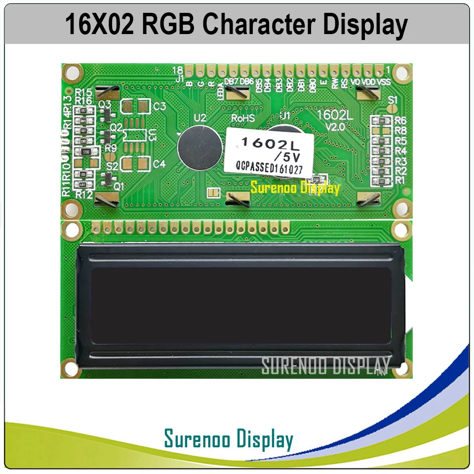
Here is the module:
floresta:
Adafruit sells a shield kit using an MCP23017 chip that should do the job for you if you don't mind the expense and if you have the means to assemble it.
It looks as if Q1, Q2, Q3 are drive transistors for the coloured LEDs.
This means you can use regular PWM or GPIO to change the colours under program control.
You waste a lot of Arduino pins with this display.
An I2C backpack could drive the LCD and Red LED. You can drive Green, Blue separately.
I suspect the novelty will wear off. You will settle for one backlight colour and stick with it.
david_prentice:
It looks as if Q1, Q2, Q3 are drive transistors for the coloured LEDs. This means you can use regular PWM or GPIO to change the colours under program control.
I think you could anyway as this is a 1602 and the LEDs are probably only 20 mA. I am certainly not going to buy one just to check!
david_prentice:
You waste a lot of Arduino pins with this display. An I2C backpack could drive the LCD and Red LED. You can drive Green, Blue separately.
Way to go!
david_prentice:
I suspect the novelty will wear off. You will settle for one backlight colour and stick with it.