2 esp8266 and button - monitor

Hi guys! I just find this forum and i'm trying to make a project but i'm stuck :sob:
I have 2 ESP8266 one is the client and one is the server. Both are connected to the home wifi.
For the client i have connected 4 button (all to 3v and D2-3-4-5).
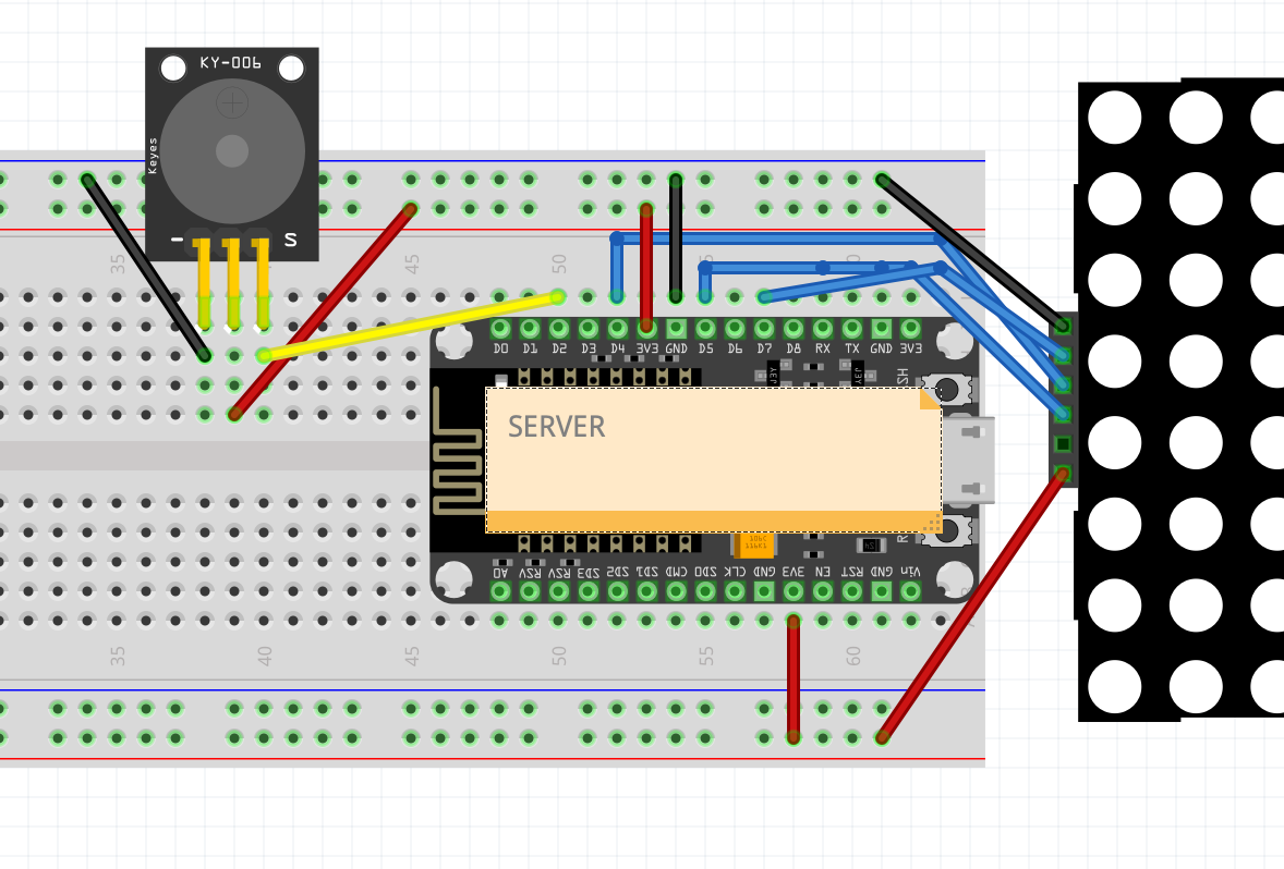
For the server i have a buzzer and a MAX7219 where i want to display the message.
The project will work like this:
If i press the first button, the client will send a message to the server and the server will buzz and put a message on the display.
But for now... the connection works but if i press the button nothing appears...
I'll post my code, if you can help me... for now it's connected only 1 button.
Client UPDATED CODE

#include <SPI.h>
#include <ESP8266WiFi.h>
#define ACTIVATED LOW 
const int ButtonBianco = D2;  
const int ButtonVerde = D3; 
const int ButtonGiallo = D4; 
const int ButtonRosso = D5; 

int StatoBianco = 0;
int StatoVerde = 0;
int StatoGiallo = 0;
int StatoRosso = 0;

char ssid[] = "Alex";               // SSID of your home WiFi
char pass[] = "Lori1234.";               // password of your home WiFi

unsigned long askTimer = 0;

IPAddress server(192,168,0,80);       // the fix IP address of the server
WiFiClient client;

void setup() {
  Serial.begin(115200);               // only for debug
  pinMode (ButtonBianco, INPUT_PULLUP);
  pinMode (ButtonVerde, INPUT_PULLUP);
  pinMode (ButtonGiallo, INPUT_PULLUP);
  pinMode (ButtonRosso, INPUT_PULLUP);
  
  WiFi.begin(ssid, pass);             // connects to the WiFi router
  while (WiFi.status() != WL_CONNECTED) {
    //Serial.print(".");
    delay(500);
  }
  //pinMode(ledPin, OUTPUT);
}

void loop () {
  client.connect(server, 80);   // Connection to the server
  StatoBianco = digitalRead(ButtonBianco);
  StatoVerde = digitalRead(ButtonVerde);
  StatoGiallo = digitalRead(ButtonGiallo);
  StatoRosso = digitalRead(ButtonRosso);
  if (StatoBianco == ACTIVATED) {
        client.println("bianco\r");
  } else if (StatoVerde == ACTIVATED) {
        client.println("verde\r");
  }  else if (StatoGiallo == ACTIVATED) {
        client.println("giallo\r");
  } else if (StatoRosso == ACTIVATED) {
        client.println("rosso\r");
  }
  //String answer = client.readStringUntil('\r');   // receives the answer from the sever
  client.flush();
  delay(2000);                  // client will trigger the communication after two seconds
}

And the server: UPDATED CODE

#include <SPI.h>
#include <ESP8266WiFi.h>
#include <MD_Parola.h>
#include <MD_MAX72xx.h>


#define HARDWARE_TYPE MD_MAX72XX::FC16_HW
#define MAX_DEVICES 4
#define CS_PIN      D4
#define CLK_PIN   D5 // or SCK
#define DATA_PIN  D7 // or MOSI
#define BIZZER_PIN D2

MD_Parola myDisplay = MD_Parola(HARDWARE_TYPE, CS_PIN, MAX_DEVICES);

char ssid[] = "Alex";               // SSID of your home WiFi
char pass[] = "Lori1234.";               // password of your home WiFi
WiFiServer server(80);                    

IPAddress ip(192, 168, 0, 80);            // IP address of the server
IPAddress gateway(192,168,0,1);           // gateway of your network
IPAddress subnet(255,255,255,0);          // subnet mask of your network

void setup() {
  Serial.begin(115200);                   // only for debug
  pinMode(BIZZER_PIN, OUTPUT);
  myDisplay.begin();
  myDisplay.setIntensity(15);
  myDisplay.displayClear(0);
  WiFi.config(ip, gateway, subnet);       // forces to use the fix IP
  WiFi.begin(ssid, pass);                 // connects to the WiFi router
  while (WiFi.status() != WL_CONNECTED) {
    //Serial.print(".");
    delay(500);
  }
  server.begin();                         // starts the server
/*  Serial.println("Connected to wifi");
  Serial.print("Status: "); Serial.println(WiFi.status());  // some parameters from the network
  Serial.print("IP: ");     Serial.println(WiFi.localIP());
  Serial.print("Subnet: "); Serial.println(WiFi.subnetMask());
  Serial.print("Gateway: "); Serial.println(WiFi.gatewayIP());
  Serial.print("SSID: "); Serial.println(WiFi.SSID());
  Serial.print("Signal: "); Serial.println(WiFi.RSSI());
  Serial.print("Networks: "); Serial.println(WiFi.scanNetworks());*/
}

int i = 0;
void funzbianco() {
    i = 0;
    myDisplay.displayScroll("BIANCO", PA_CENTER, PA_SCROLL_LEFT, 50);
    while(i < 3){
    digitalWrite(BIZZER_PIN, HIGH);
    delay(1000);
    digitalWrite(BIZZER_PIN, LOW);
    delay(1000);
    i++;
    }
}

void loop () {
  WiFiClient client = server.available();
  if (client) {
    if (client.connected()) {
      Serial.println("Client connected");
      String request = client.readStringUntil('\r');    // receives the message from the client
      if (myDisplay.displayAnimate()) {
      myDisplay.displayReset(); }
      
      Serial.print("From client: "); Serial.println(request);
      if (request == "bianco"){
        funzbianco();
      }
      client.flush();
    }
    client.stop();                // terminates the connection with the client
  }
}

I don't understand what it's wrong.. can you please help me?
Thanks!

HOW are the buttons connected ?

It's connected like this:

A B
C D

A to 3V
B to D2 pin
D to GND

I just saw that i've made a mistake, the code for the server is client and client server...
This evening i'll modify in this way:
The server have the control on the led panel and the buzzer.
The client will have the 4 button.

The Wonders of Fritzing (always horrible).

A NodeMCU can't be placed on a breadboard that way.
And the pushbutton scheme is Wrong - it shorts 3V to GND.
(But maybe you're happy with that.)

I know it can't be placed like this, because isn't placed in the breadboard in the physical project. I put it close for the screenshot.

Nobody can tell what you are doing if you are not accurately presenting what you are doing.
The pushbutton is, still, a disaster (as shown).

I'm here to learn, i'm not a programmer :grimacing:
I think this is the correct way for the pushbutton, right?

A B
C D
A to GND, B to D2
C do 3v, right?

The switch wiring isn't programming.

No, and I noted that twice before.
One pole of the switch goes to GND, the other goes to, for example, ButtonRoss.
Instead of --

  pinMode(ButtonRosso, INPUT);
  digitalWrite(ButtonRosso,HIGH);

use

  pinMode (ButtonRosso, INPUT_PULLUP);

Thanks you for your patience and for your help. Now i made a new scheme with how i connected the cables and the other things. I updated the code in the first post.


The server have the rgb 8x8 4 panel and the buzzer. (in the image it's in the breadboard but not physically)
I tried the panel and worked in a simple print project..
I put a buzzer in the server if (request == "bianco") but nothing happen...

I connected correctly this time.. (i think and hope), i tried it with a simple buzzer test code and it worked. Now for the project it's like this.

But now i'm stuck after the connection to the home wifi. They bot connect but if i press the button nothing happen in the monitor. For testing purpose it's only one button for now, the ButtonBianco.

I tried to use the serial monitor at 115200 baud but it only write nonsense string...

rll⸎r$⸎n⸎l⸎b|⸎⸎a⸎rb⸎b⸎nnlnnbbp⸎$blrlp⸎n⸎l⸎bn⸎n⸎⸎b⸎⸎nn'l⸎l`⸎nn$`nr⸎⸎⸎nrr⸎`p⸎n⸎r⸎bbn⸎nb⸎⸎nn'l`⸎nn$`nr⸎⸎⸎nrl`r⸎⸎nrl`⸎$⸎ll`⸎⸎n⸎`

Thanks again if you'll help me...

I made some revisions and pared the matter down to BIANCO.
If the pushbutton is wired properly, SerialMonitor will have
Bianco pb displayed.
To troubleshoot, all you generally need is SerialMonitor and/or an onboard LED.

#include <SPI.h>
#include <ESP8266WiFi.h>
//#define ACTIVATED LOW 
const byte ButtonBianco = D2;  
const byte ButtonVerde = D3; 
const byte ButtonGiallo = D4; 
const byte ButtonRosso = D5; 

//int StatoBianco = 0;
//int StatoVerde = 0;
//int StatoGiallo = 0;
//int StatoRosso = 0;

char ssid[] = "Alex";               // SSID of your home WiFi
char pass[] = "Lori1234.";               // password of your home WiFi

unsigned long askTimer = 0;

IPAddress server(192,168,0,80);       // the fix IP address of the server
WiFiClient client;

void setup() 
{
  Serial.begin(115200);               // only for debug
  pinMode (ButtonBianco, INPUT_PULLUP);
  pinMode (ButtonVerde, INPUT_PULLUP);
  pinMode (ButtonGiallo, INPUT_PULLUP);
  pinMode (ButtonRosso, INPUT_PULLUP);
  
  WiFi.begin(ssid, pass);             // connects to the WiFi router
  while (WiFi.status() != WL_CONNECTED) 
  {
    //Serial.print(".");
    delay(500);
  }
  //pinMode(ledPin, OUTPUT);
}

void loop () 
{
  client.connect(server, 80);   // Connection to the server

  if (!digitalRead(ButtonBianco)) 
  {
    Serial.println("Bianco pb");  // ← ← Troubleshoot
    client.println("bianco\r");
  } 
  //if (!digitalRead(ButtonVerde))
  //{
  //  client.println("verde\r");
  //}
  //if (!digitalRead(ButtonGiallo)) 
  //{
  //  client.println("giallo\r");
  //}
  //if (!digitalRead(ButtonRosso)) 
  //{
  //  client.println("rosso\r");
  //}

  client.flush();
  delay(2000);
}

If i open the serial monitor it print this:


I set the baud rate at 115200 but nothing change...

I tried at 9600 but nothing change (it's write on the nodemcu v3 that it need to use 9600)

I'm debugging the server with the led matrix, if i put the displayscroll in the setup (at the start and the end) the message appear. But if i put in the void loop, nothing happen. Maybe the code is broken or something not working?

Another info: both of the esp8266 connect to the wifi (i can see them from the admin page).

first of all take a look at this short tutorial on how to present schematics.

the professional way to build up a project is:

testing every detail on its own.

This means first thing to test is the function of the button

alone

nothing else than the button connected to your ESP8266 and a small testcode that reads in
the IO-pin and prints the IO-pin-state to the serial monitor

// MACRO-START * MACRO-START * MACRO-START * MACRO-START * MACRO-START * MACRO-START * 

// a detailed explanation how these macros work is given in this tutorial
// https://forum.arduino.cc/t/comfortable-serial-debug-output-short-to-write-fixed-text-name-and-content-of-any-variable-code-example/888298

#define dbg(myFixedText, variableName) \
  Serial.print( F(#myFixedText " "  #variableName"=") ); \
  Serial.println(variableName);
// usage: dbg("1:my fixed text",myVariable);
// myVariable can be any variable or expression that is defined in scope

#define dbgi(myFixedText, variableName,timeInterval) \
  do { \
    static unsigned long intervalStartTime; \
    if ( millis() - intervalStartTime >= timeInterval ){ \
      intervalStartTime = millis(); \
      Serial.print( F(#myFixedText " "  #variableName"=") ); \
      Serial.println(variableName); \
    } \
  } while (false);
// usage: dbgi("2:my fixed text",myVariable,1000);
// myVariable can be any variable or expression that is defined in scope
// third parameter is the time in milliseconds that must pass by until the next time a 
// Serial.print is executed
// end of macros dbg and dbgi
// MACRO-END * MACRO-END * MACRO-END * MACRO-END * MACRO-END * MACRO-END * MACRO-END * 


void PrintFileNameDateTime() {
  Serial.println( F("Code running comes from file ") );
  Serial.println( F(__FILE__) );
  Serial.print( F("  compiled ") );
  Serial.print( F(__DATE__) );
  Serial.print( F(" ") );
  Serial.println( F(__TIME__) );  
}


// easy to use helper-function for non-blocking timing
boolean TimePeriodIsOver (unsigned long &startOfPeriod, unsigned long TimePeriod) {
  unsigned long currentMillis  = millis();
  if ( currentMillis - startOfPeriod >= TimePeriod ) {
    // more time than TimePeriod has elapsed since last time if-condition was true
    startOfPeriod = currentMillis; // a new period starts right here so set new starttime
    return true;
  }
  else return false;            // actual TimePeriod is NOT yet over
}

unsigned long MyTestTimer = 0; // Timer-variables MUST be of type unsigned long

const byte buttonPin = 4;


void setup() {
  Serial.begin(115200);
  Serial.println("Setup-Start");
  PrintFileNameDateTime();
  pinMode(buttonPin, INPUT_PULLUP);
}


void loop() {
  // print the state of the IO-pin to the serial monitor 
  // once every 1234 milliseconds
  dbgi("1:",digitalRead(buttonPin),1234);
}

After that write a small testcode that does nothing more than shows message 1 then message 2 on the display

After that write another test-code that justs connects to your wifi printing the connection-status to the serial monitor

etc. etc.

If you put it all together at once without knowing if a certain part is working or not
you need 10 times longer to find the bug because while trying to solve the bug you might change a working part to not working etc.

best regards Stefan

This is how these type of buttons are connected internally
grafik

This means if you connect them the wrong way the connection between both ends is permanently given. => pressing the button does not change the IO-pin-state

Connecting +3.3V and GND permamently may have lead to that you have destroyed the voltage-regulator through the shortcut.

the microcontroller-world is not superstandardised like USB-devices
You have to take care of more things than just

"does the plug fit into the socket?"

best regards Stefan

This topic was automatically closed 180 days after the last reply. New replies are no longer allowed.